4 - 1
Section E Hydraulics
9803/8550
Section E
4 - 1
Issue 4*
Descriptions
General Description up to machine no. 752462
The main components of the hydraulic circuit are the tank, pumps, drive motors, the servo operated loader and drive control
circuits, the manually operated excavator valves, filters, cooler, rams and pressure reducing solenoid valve.
The pumps are driven by the engine and are mounted in tandem. They deliver pressurised oil to the valves and motors. The
valves are operated by either a servo joystick in the case of the loader or drive circuits, or a manual control lever for the
excavator circuit. When a valve is operated, it delivers the oil to one end of the appropriate ram or to the pump servo-controls
depending on which control is operated. The pressurised oil forces the ram's piston along the bore of the ram or operates the
pump servo controls, which changes the flow direction to the motors and hence the direction of rotation. A Pressure Reducing
Solenoid Valve maintains the required pressure at various components and relief valves prevent system pressure from rising
too far.
The Pressure Reducing Solenoid Valve (together with its associated electrical circuitry) is designed to both limit the pressure in
the circuit and act as a safety device. The safety function ensures that the machine controls cannot be operated without the
operator being seated correctly in his seat and the door properly closed and latched.
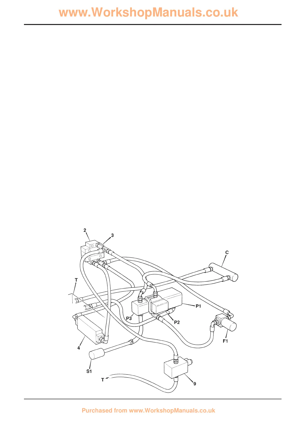
Machine Neutral Circuit
(This description should be read in conjunction with the diagram below and the Hydraulic Schematic Diagrams starting on page
E/30 - 1)
Oil is drawn from the tank T by the auxiliary pump P3 via a suction strainer S1. The pump P3 delivers pressurised oil to the
pressure reducing solenoid valve 9 and, providing that solenoid valve 9 is in the energised position, to the loader control valve
2. In the de-energised position, valve 9 returns the oil to the hydraulic tank. This ensures that there is insufficient pressure
available to operate the 5 bar check valve 3.
If valve 9 is energised, oil is permitted to flow to the loader control valve 2. After passing through the loader valve, the oil flows
through the excavator valve 4 and then via the filter F1 to the main pumps P1 and P2. Oil from P1 and P2 is returned via the
cooler C to the tank T. Valve 9 also allows the transmission brakes to be manually applied.
204361
*
*

 Loading...