4 - 4
Removal and Replacement
Perkins Engines
Disconnect the battery negative lead.
Disconnect the wiring from the rear of the alternator.
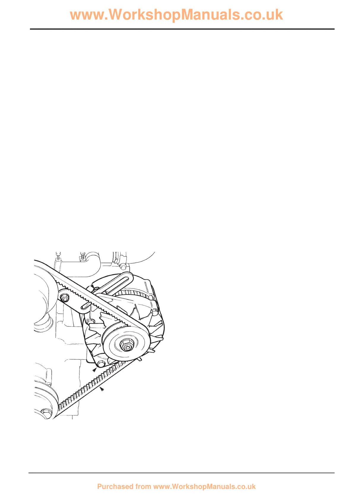
Loosen the pivot bolt A and the adjustment bolt B.
Reposition the alternator to release the tension then slip the
drive belt from the pulleys.
Remove the adjustment bolt B. Swivel the alternator
outwards, remove the pivot bolt A and lift it from the engine.
Examine the drive belt for wear.
Replacement is a reversal of the removal procedure.
Position the alternator until belt deflection at X is
approximately 10 mm (3/8 in) then tighten bolts A and B.
Dismantling and Assembling
Dismantling
Remove suppressor 2 (if fitted) by removing nut 1 and
disconnecting lead E from terminal F.
Unscrew bolts 3 and disconnect lead G from terminal H to
remove the brush box and regulator assembly 4. If the brush
length is less than 5mm (0.2in) [new length 17mm(0.67in)], or
if spring pressure is less than 1.3 N the brush box and
regulator assembly must be renewed.
Remove nuts and washers 5, bolts 6 and nuts 7. Remove
slip ring end bracket 8.
Carefully remove rectifier 10 and stator 11 as an assembly.
Unsolder the interconnecting wires at X, Y, and Z only if
renewing either of these components.
Remove nut and washer 12 using an 8mm Allen key in the
shaft hexagon hole to prevent rotation. If necessary, use a
press to remove rotor 19 from the drive end bracket 17.
Check the rotor poles and the inner faces of the stator for
signs of rubbing, which indicates worn bearings. The drive
end bearing is part of bracket 17 and cannot be removed
separately. If requiring renewal, needle roller bearing 20
should be pressed out in the direction of the arrow.
Assembling
Reverse the dismantling procedure, but note the following:
Ensure that spacers 14, 16 and 18 are correctly positioned
as shown.
Ensure that the slip rings J are clean and smooth, using
extra fine glasspaper to rectify slight imperfections.
`
Ensure that insulation bushes 9 and washer 5 are positioned
as shown.
Take care not to damage the brushes when fitting the brush
box and regulator assembly.
Torque Settings
Item Nm Kgf m lbf ft
3 2.7 0.28 2.0
5 4.1 0.41 3.0
6 3.4 0.35 2.5
7 5.4 0.55 4.0
12 60.0 6.10 44.2
Section C Electrics
9803/8550
Section C
4 - 4
Issue 1
Alternator
S255830
A
X
B

 Loading...