– 70 –
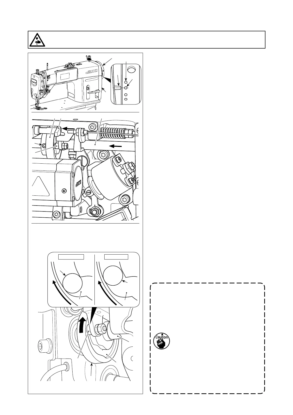
7-3. Adjusting the thread trimmer
7-3-1. For checking of the thread trimming cam
timing
The purpose of the adjustment of the thread trim-
ming cam is to align marker line A on pulley cover
❺ with green marker dot B (H type : White marker
dot B´) on handwheel ❻.
1) Tilt the sewing machine head.
2) Turn handwheel ❻ by hand in the normal direc-
tion of rotation until the thread take-up lever goes
up slightly below the upper dead point. Press cam
follower ❶withngerstotheleft(indirectionof
arrow E)totroller❷ to in groove C in thread
trimming cam ❸.
3) In this state, turn handwheel ❻ in the direction
which is opposite to the normal direction of rota-
tion until handwheel ❻ will go no further. (If the
handwheel is turned further, it reaches the posi-
tion at which cam follower ❶ starts moving.)
At this time, marker line A on pulley cover ❺
aligns with green marker dot B on handwheel ❻.
7-3-2. Adjustment of the thread trimming cam
timing
1) Tilt the sewing machine head.
2) Loosen the screws No.1 and No. 2 of thread trim-
ming cam setscrew ❼ in the written order.
3) Align marker line A on pulley cover ❺ with green
marker dot B on handwheel ❻. (H type : White
marker dot B´)
4) Pressing cam follower ❶ to the left (in the direc-
tion of arrow E), engage thread trimming cam ❸
with roller ❷. Then, turn only thread trimming cam
❸withngersinthedirectionwhichisopposite
to the normal direction of rotation of feed driving
shaft ❹ until it will go no further without turning
feed driving shaft ❹. At this position, tighten the
screws No. 1 and No. 2 of thread trimming cam
setscrew ❼ in the written order while pressing
thread trimming cam ❸ against roller ❷.
1. In the case of using a high-count
lament thread, thread loop
formation may be unstable. If faulty
loop spreading occurs in this state,
correct the thread trimming cam
timing by aligning the marker line on
the pulley cover with the red marker
dot, instead of the green marker dot,
on the handwheel.
2. The alignment point between thread
trimming cam ❸ and roller ❷ is
position (F) from which cam follower
❶ starts moving. Position (G) at
which you feel that thread trimming
cam ❸ comes in contact with roller ❷
for the rst time during adjustment is
not the correct alignment position.
*
Be sure to correct the thread trimming
cam timing carefully since it largely
affects the loop spreading timing.
WARNING :
Turn OFF the power before starting the work so as to prevent accidents caused by abrupt start of the
sewing machine.
❻
❺
Turn thread trimming cam ❸ in the direction of
arrow until the outer periphery of thread trimming
cam groove C comes in contact with roller ❷ and
stops. At this position, x thread trimming cam
setscrew ❼.
Illustration as observed from D (right side face)
❷
C
❸
❹
❷
❼
❶ ❹❸
D
E
❷
C
Correct (F)
❷
C
Wrong (G)
A
B
B
´

 Loading...