− 121 −
11. EXTERNAL OUTPUT/INPUT CONNECTORS
The following convenient signals are prepared to CN56 on CTL circuit board in the case where the counter
or the like is set up after setting up the sewing machine.
(Caution) Consult the engineeers who have electrical knowledge when using the connectors.
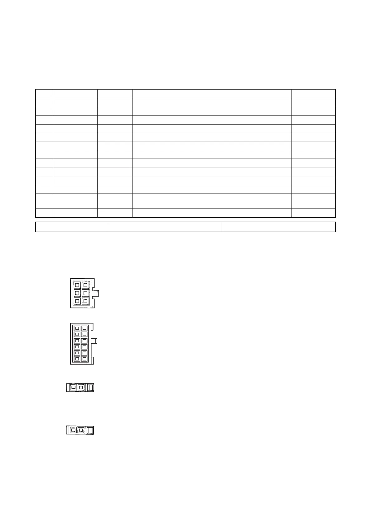
Table of allocation of the connector and signal
CN56
1
2
3
4
5
6
7
8
9
10
11
12
13
Name of signal
+5V
UDET
DDET
HS/LS
BT
TRM
LSW
S.STATE
LSWINH
SOFT
GND
Output/input
Output
Output
Output
Output
Output
Output
Output
Input
Input
Description
Prohibited to use
Prohibited to use
“L” is output when the needle bar is in its upper position.
“L” is output when the needle bar is in its lower position.
Rotation pulse output of 360 and 45 rotation by changeover of W2
"L" is output when the back solenoid is driven.
"L" is output when the thread trimming solenoid is driven.
"H" is output when the rotation is commanded.
“L” is output when the sewing machine is in stopping state.
Rotation by pedal is prohibited while “L” signal is inputted.
Speed of rotation is limited to soft-speed while “L” signal is
imputted.
Electric spec.
DC5V, 50 mA
DC5V, 1 mA
DC5V, 1 mA
DC5V, 1 mA
DC5V, 1 mA
DC5V, 1 mA
DC5V, 1 mA
DC5V, 1 mA
DC5V, –5 mA
DC5V, –5 mA
JUKI genuine Part No. Part No. of connector : HK016510130 Part No. of pin contact : HK016540000
1-2 FL (Presser lifting) Approx. 5.4 Ω
1
3
4
6
1 2
1 2
CN 54
CN 53
CN 46
CN 40
(1) Connector connection diagram
Machine head solenoid
Presser lifting solenoid
1-4 TRM (Thread trimming) Approx. 7.5 Ω
2-5 BT (Reverse feed stitching) Approx. 6.5 Ω
5-11 WP (Wiper) Approx. 8.5 Ω
6-12 TL (Thread release) Approx. 12.5 Ω
1-2 TLSUB (Thread feeding) Approx. 27 Ω
7
12
1
6
 Loading...