− 38 −
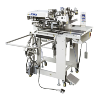
(25) Timing of the thread trimming cam(Thread trimmer type only)
Standard Adjustment
(See the figure shown above.)
™ Press roller arm 6 until roller 4 fits in the groove in thread trimming cam 8. Now, lightly turn the
main shaft handwheel carefully in the reverse direction until it stops. At this time, the marker dot
engraved on the machine arm should be aligned with the red marker dot engraved on the handwheel.
Adjust the thread trimming cam longitudinally within the width of a dot.
Machine arm
Width of
adjustment
Red engraved marker
dot on handwheel
Engraved marker dot on
machine arm
Handwheel
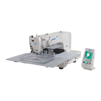
(26) Installing/removing the knife unit (Thread trimmer type only)
Standard Adjustment
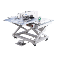
(27) Stop position of the needle after thread trimming (Needle UP stop)
Standard Adjustment
1
™ The standard stop position of the needle (position at which the marker dot engraved on the machine
arm is aligned with the white marker dot engraved on the handwheel) is when the marker line
engraved on the thread take-up is aligned with the marker line engraved on the face plate (60˚).
™ Adjusting range is within one engraued marker dot in front and rear.
Handwheel
Machine
arm
(Advances)
(Retards)
Adjusting
range
Handwheel
A
B
1
2
3
2
6
5
4
Knife unit
Knife unit
A:
Needle UP stop
B: Needle DOWN stop
D
H
F
C
G
A
B
E
J
I
 Loading...