Home
JUKI
Sewing Machine
IT-100D
JUKI IT-100D Engineer's Manual
4
of 1
of 1 rating
154 pages
Give review
Manual
Specs
To Next Page
To Next Page
To Previous Page
To Previous Page
Loading...
−
89
−
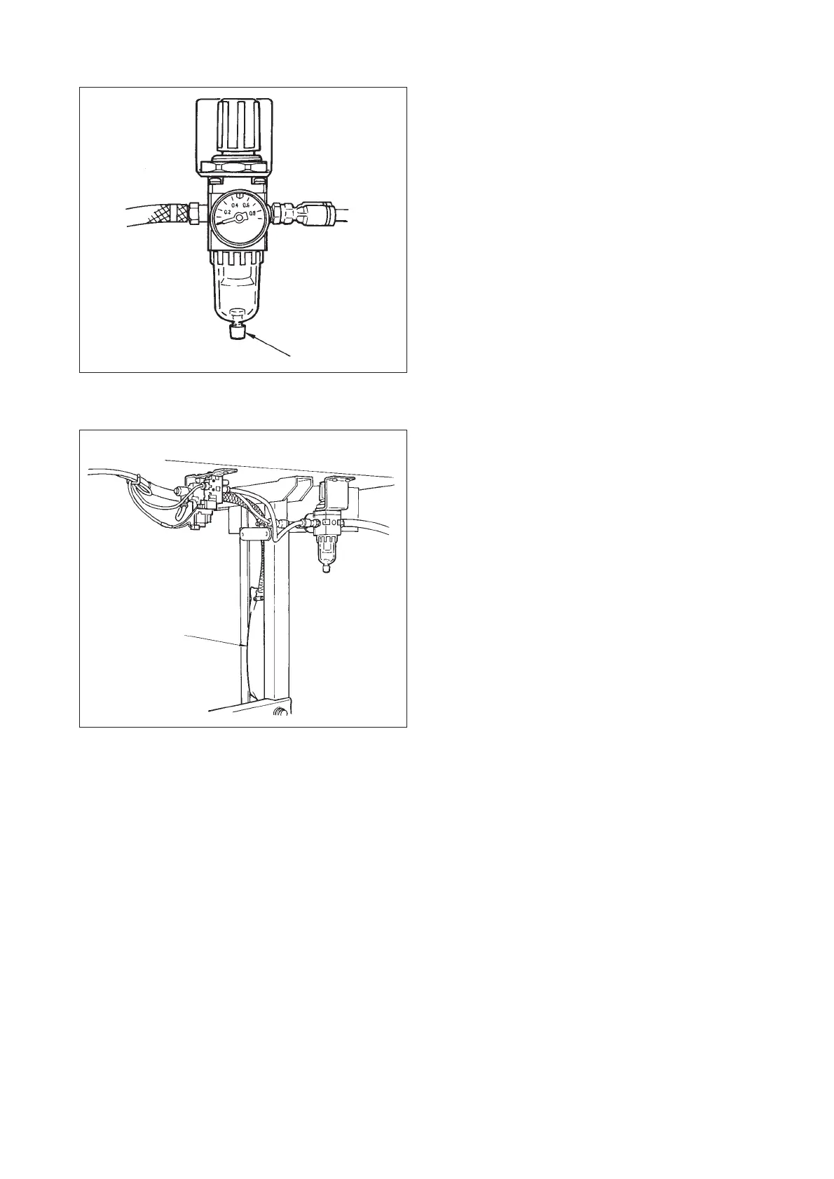
(11) Draining of CB type
When the regulator becomes filled with water, turn knob
1
for drain counterclockwise.
(12) Cleaning the dust bag of CB type
Periodically clean dust bag
1
.
(When the dust bag becomes excessively filled with
waste thread, there may be cases where clamp failure
occurs.)
1
1
92
94
Table of Contents
Table of Contents
3
Specifications
5
Specifications of the Machine Head
5
Stitch Pattern Table
6
Function List
7
Cautions in Operation
8
Name of each Component
8
Standard Adjustment
10
Height and Inclination of the Feed Dog
10
Adjusting the Feed Timing
10
Adjusting the Feed Timing (Excluding A-SR)
10
Adjusting the Feed Timing (for A-SR Only)
12
Adjusting the Feed Amount
14
Adjusting the Feed Amount (Excluding A-SR)
14
Adjusting the Feed Amount (A-SR Only)
16
Position of the Feed Dog
18
Adjusting the Slippage of Materials (for A-SU and A-DU)
20
Adjusting the Origin of the Needle Rocking Motor
22
Adjusting the Needle Entry Position (in Terms of Needle Rocking Direction)
24
Adjusting the Needle Entry Position (in Terms of Longitudinal Direction)
24
Adjusting the Longitudinal Play at the Needle Bar
24
Position of the Needle Bar Connection Guide
26
Height of the Needle Bar
26
Adjusting the Needle-To-Hook Timing and the Needle Guard
28
Position of the Bobbin Case Stopper
30
Orientation of the Needle Bar Thread Holder
30
Position of the Thread Tension
32
Position of the Pre-Tension
32
Position of the Thread Take-Up Spring Guard
34
Installing the Thread Take-Up Thread Guide B
34
Installing the Thread Take-Up
34
Installation of the Presser Foot
36
Installing and Adjusting the Bobbin Winder Unit
36
Adjusting the Amount of Oil in the Hook (A-SS/-7, A-SU/-7, A-SR)
38
Adjusting the Thread Trimming Unit (Thread Trimmer Type Only)
40
Initial Position of the Moving Knife (Thread Trimmer Type Only)
40
Timing of the Thread Trimming Cam(Thread Trimmer Type Only)
42
Installing/Removing the Knife Unit (Thread Trimmer Type Only)
42
Stop Position of the Needle after Thread Trimming (Needle up Stop)
42
Clearance Provided between the Main Shaft Handwheel and the Stator
44
Position of the Automatic Reverse Stitching Magnet (Excluding A-SR)
44
Adjusting the Thread Tension Releasing Solenoid (Thread Trimmer Type Only)
44
Adjusting the Stitch Length Dial (Excluding A-SR)
46
Adjusting the Lubrication Mechanism (A-SS and A-SU, A-SR Only)
48
Adjusting the Position of the Thread Draw-Out Wire (for the Machine with Thread Trimmer Only)
48
Adjusting the Stroke of the Thread Draw-Out Wire (for the Machine with Thread Trimmer Only)
50
Installing the Wiper Base (WB Type Only)
50
Adjusting the Wiper Solenoid (WB Type Only)
52
Position of the Wiper
52
WB Type
52
CB Type
54
Procedures of Disassembing/Assembling and Cautions
56
Adjusting and Assembling of the Gear Box (Large)
56
Replacing the Motor
58
Replacing the Timing Belt
60
Removing/Installing the Gear Box Cover
62
Disassembling/Assembling the Needle Bar Support Base Shaft (Asm.)
62
Adjusting/Assembling the Reverse Feed Control Lever (A-SR Only)
74
Maintenance
80
Changing Procedure between Single Phase 100 to 120V and 3-Phase 200 to 240V
80
Replacing Procedure of the Printed Circuit Board
81
Maintenance of the Hook Lubricating Pipe Oil Filter
82
Cleaning the Cooling Fan
83
Applying the Exclusive Grease
84
Hook Shaft Gear
88
Adjusting the Needle Rocking Link
89
Lubricating to Face Plate Section (A-SS and A-SU, A-SR Only)
90
Protruding Amount of the Hook Shaft
92
Adjusting the Feed Stepping Motor Unit (A-SR Only)
92
Draining of CB Type
93
Cleaning the Dust Bag of CB Type
93
Operation Panel
94
Names of the Respective Sections
94
Information
96
Matters that Demand Special Attention Regarding the Operation Panel, IP-100
110
Specifications of Sc-915/916
111
Function Setting Procedure of Sc-915/916
111
How to Change over to the Function Setting Mode
111
Function Setting List
115
Detailed Explanation of Selection of Functions
119
External Output/Input Connectors
125
Connector Connection Diagram
125
Error Display
126
Error Code List (Error Display in Panel)
127
Warning List
130
Screws for Attachments
131
Spare Parts
131
Optional Cord
132
Relay Cord a Asm. for Standing Machine (Part No. M9701351AA0)
132
Relay Cord a Asm. for DC24V (Part No. M9703351AA0)
133
Troubles and Corrective Measures
134
With Regard to Lubrication
134
With Regard to Sewing
136
With Regard to Mechanical Components
141
Confirmation
148
Block Diagram
149
Block Diagram a (for SC-915)
149
Block Diagram B (for SC-916)
150
Operation Panel Block Diagram
151
Drawing of Table
152
Custom Pattern Needle Entry Position Data Sheet
153
Other manuals for JUKI IT-100D
Instruction Manual
124 pages
4
Based on 1 rating
Ask a question
Give review
Questions and Answers:
Need help?
Do you have a question about the JUKI IT-100D and is the answer not in the manual?
Ask a question
JUKI IT-100D Specifications
General
Brand
JUKI
Model
IT-100D
Category
Sewing Machine
Language
English
Related product manuals
JUKI IT-100
85 pages
JUKI IP-110 Type F
42 pages
JUKI APW-895/IP-420
124 pages
JUKI APW-896/IP-420
140 pages
JUKI APW-895N/IP-420
52 pages
JUKI AMS-210EN/IP-420
133 pages
JUKI AMS-221EN/IP-420
121 pages
JUKI AMS-224EN/IP-420
120 pages
JUKI LZ-2290A/IP-110A/SC-915
119 pages
JUKI LZ-2290A-SR/IP-100D/SC-916
151 pages
JUKI DDL-8700
40 pages
JUKI LK-1900A
83 pages
 Loading...