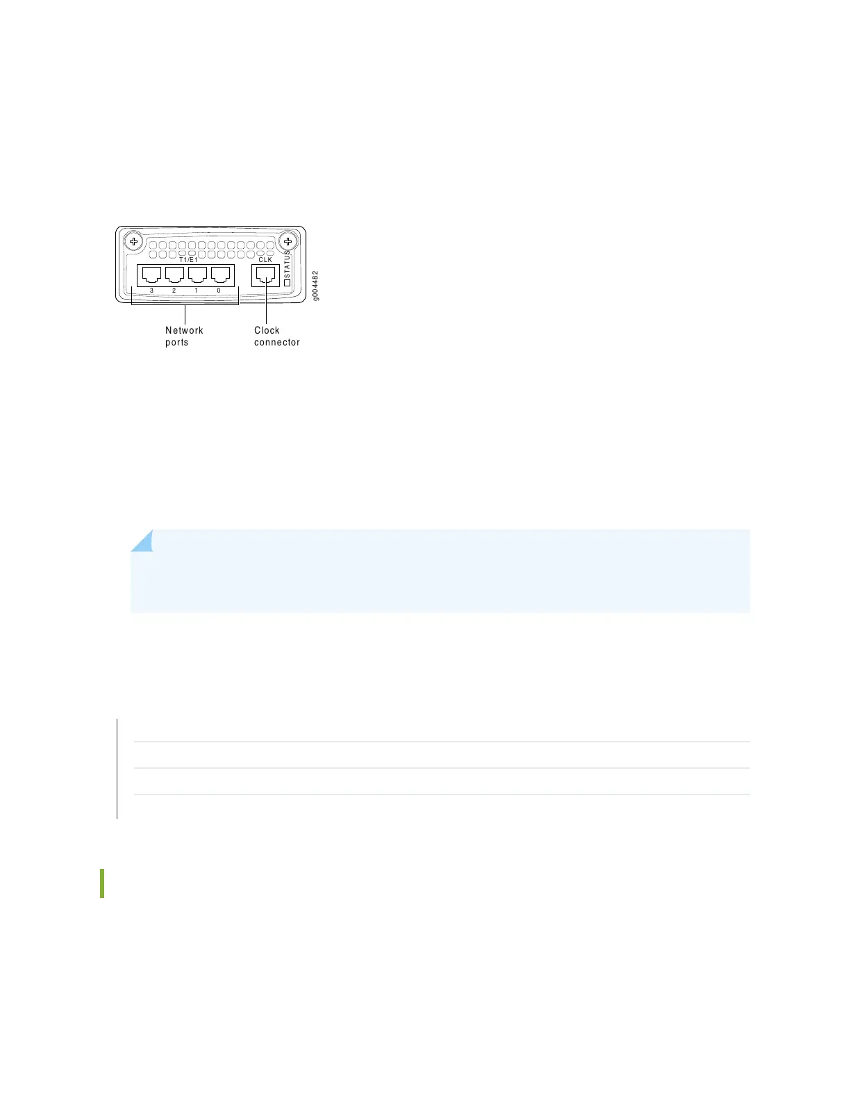
The four-port T1/E1 interface module supports individual cabling for each port. The CTP150 ports have
T1/E1 ports for RJ-48 connectors (see Figure 5 on page 10). The highest-numbered port (labeled 3) is on
the left, and the lowest-numbered port (labeled 0) is at the right, with the CLK port still farther to the right.
Figure 5: CTP150 T1/E1 Interface Module
g004482
T1/E1 CLK
STATUS
3 2 1 0
Clock
connector
Network
ports
The software-selectable T1/E1 interfaces for the module are T1, E1, fractional T1, and fractional E1. CSU
options, encoding, and encapsulation are also software-selectable.
The module also includes an external clock reference port for an RJ-48 connector. Note that only one
external clock reference is required even if there are two interface modules, serial or T1/E1.
If you want to use an external clock as node reference, then the clock must be connected to module slot
0. Slot 0 is the left module slot.
NOTE: The external clock reference port must be the one in module slot 0, the left-most module
slot in the front of the CTP150 chassis.
RELATED DOCUMENTATION
CTP150 Serial Interface Module | 7
CTP150 Multiservice Interface Module | 8
CTP150 Interface Module HD-26 Connector Cable Pinouts | 27
CTP150 Console Cable Pinouts | 34
CTP150 Clock Module
Clock interface modules provide clock distribution between modules when the backplane is in use by voice
applications. For the CTP150 model, the serial and T1/E1 interfaces each have a clock port, although only
10
 Loading...