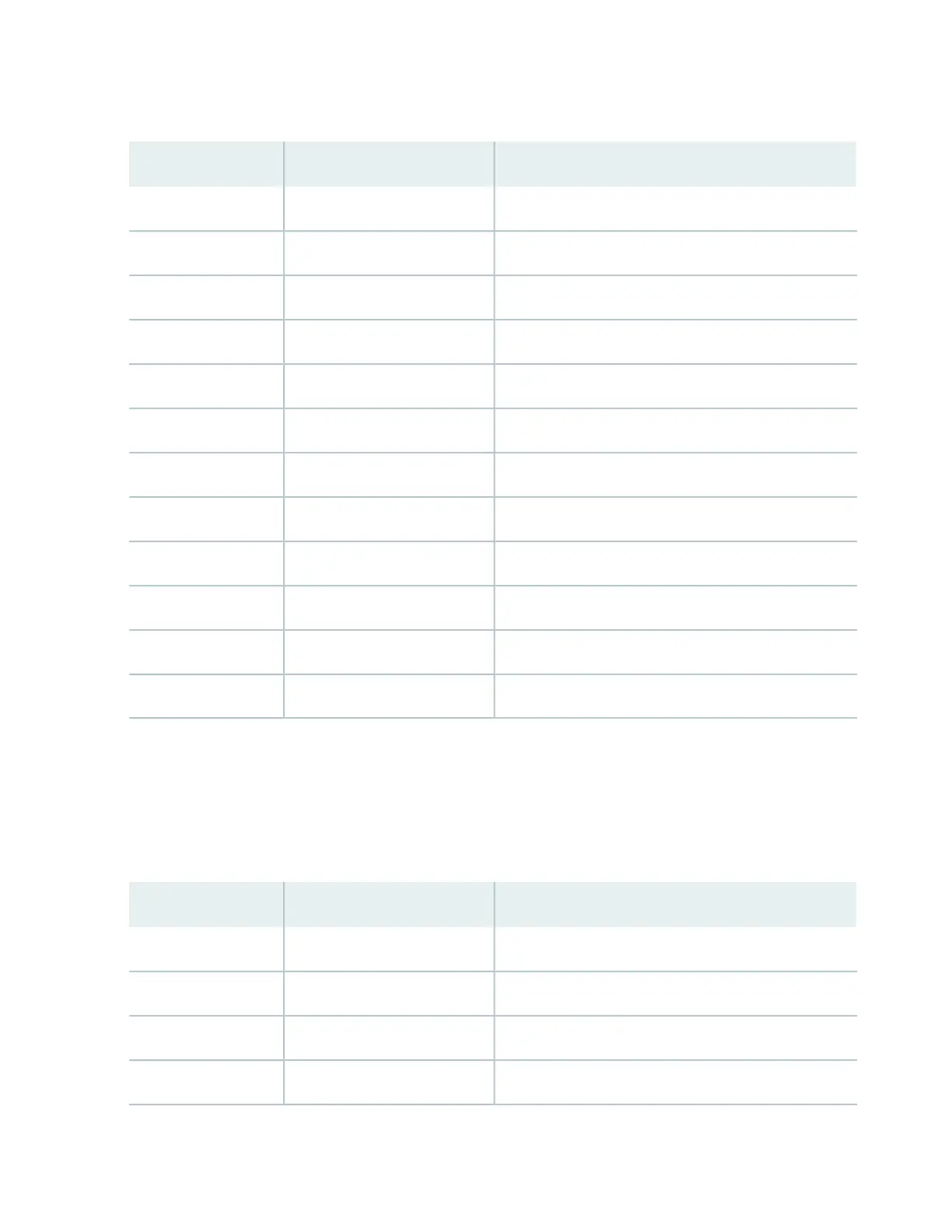
Table 6: X.21 DTE Connector Interface Signals for HD-26 to Male DB-15 (continued)
DescriptionDB-15 PinHD-26 Pin
Transmit Clock—A (output from CTP)62
Receive Clock—A (input to CTP)74
Receive Data—A (input to CTP)25
Signal Out—A (output from CTP)58
Signal Out—B (output from CTP)129
Signal In—B (input to CTP)1010
Signal In A (input to CTP)311
Transmit Data—B (output from CTP)1114
Transmit Clock—B (output from CTP)1315
Receive Clock—B (input to CTP)1417
Receive Data-–B (input to CTP)918
Ground824, 26
V.24 Connector Interface Signal Pinouts (RJ-45 Male)
Table 7 on page 32 lists the V.24 interface signal pinouts for the HD-26 connector to the male RJ-45
connector for the CTP150 platform.
Table 7: V.24 Connector Interface Signals for HD-26 to RJ-45
DescriptionRJ-45 PinHD-26 Pin
TX51
RCLK12
TCLK33
RX65
32
 Loading...