SSG 500 M Series Hardware Installation and Configuration Guide
20 Back Panel
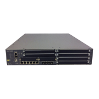
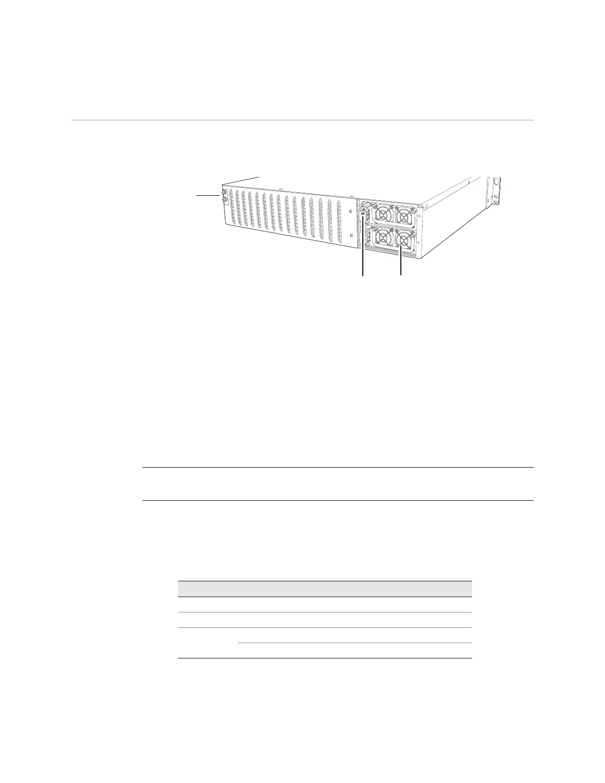
Back Panel
The back panel of an SSG 500M Series device contains the fan tray and power
supply unit(s) and a two-hole grounding lug.
Figure 13: Back Panel of an SSG 500M Series Device
Power Supply Units
The power supply units (PSUs) are located at the right side of the back panel:
The SSG 520M device is equipped with a single permanently installed AC or DC
power supply unit (PSU).
The SSG 550M device has slots for two field-installable PSUs and is supplied
with a single AC or DC PSU. You can add a second AC or DC PSU for increased
reliability.
For PSU servicing instructions, see “Device Power Components (SSG 550M Only)”
on page 52.
The POWER LED on the front panel of an SSG 500M Series device glows either
green or red. Green indicates correct function and red indicates PSU failure.
Table 7 describes the LED states on the field-installable AC and DC PSUs.
Table 7: Input Power LED Descriptions
Grounding
lugs
Power Supply Units
NOTE: Do not mix SSG 550M PSU types. The only supported combinations are AC+AC
and DC+DC.
Color Status Description
Green On steadily Input power is on and device is on
Yellow On steadily Input power is on but device is off
Amber On steadily Input power is on and device is off
Off Input power is off
 Loading...