Chapter 5---Electronics
5-74 Model 250 Service Manual
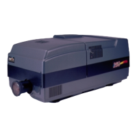
5.12 Backplane PCB
The Backplane PCB is the spine of the Electronics Module. Every major
electronic component in the Model 250 projector connects to and through the
Backplane PCB. It is hidden in the inside of the Electronics Module (see Figure
5-2). The System Controller PCB, Raster Timing Generator PCB, Video
Processor PCB and the three VICs are connected into it directly. All the other
PCBs and Power Supplies are connected through jumpers and cabling.
Troubleshooting on the Backplane PCB
The connectors on the Backplane PCB provide one of the more accessible places
to probe voltages and signals that may be useful for troubleshooting purposes (see
Figure 5-43 and associated list of signals and voltages).
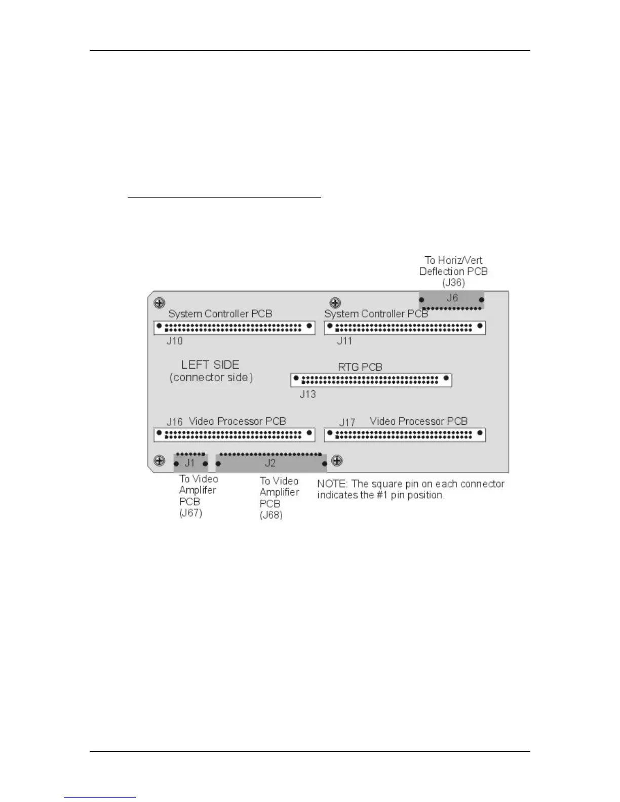
Figure 5-42
Backplane Diagram (left side).
 Loading...