Chapter 5---Electronics
5-24 Model 250 Service Manual
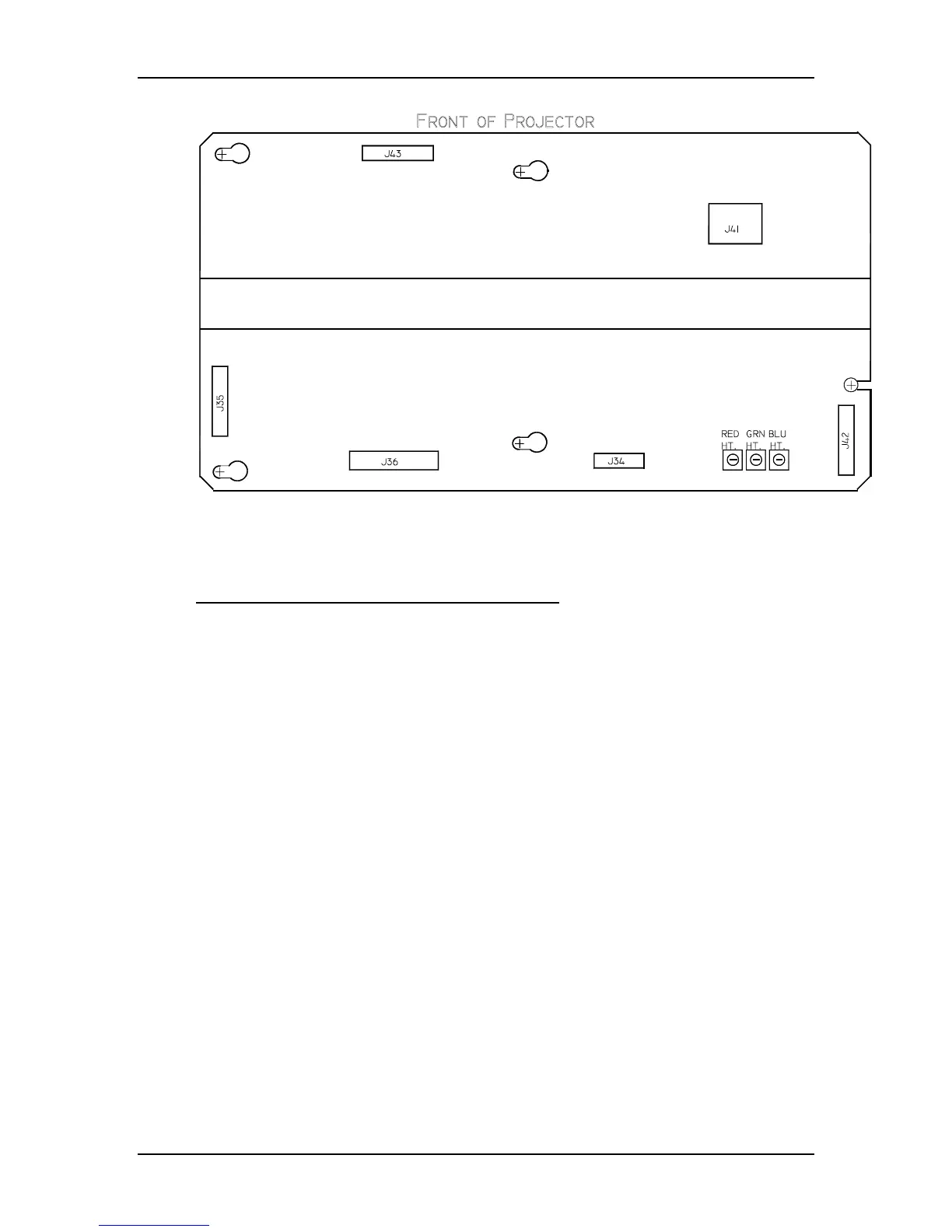
Figure 5-15
Physical layout of the Horizontal/Vertical PCB (note the Vertical Size
Adjustment Pots (Red-137, Grn-148, and Blu-160) on the lower right).
Horizontal Vertical Deflection PCB - Outputs
/SWEEP_OK - signal to the Video Amplifier PCB, derived from the H_ENA
signal from the Raster Timing Generator PCB, and the DEFL_OK from the Scan
Reversal PCB.
WIDTH_CTRL - a DC voltage to the Convergence Deflection PCB that adjusts
the parabola waveforms used for geometric correction (about 4 V max.).
H_RGB(pos.) - horizontal deflection waveform return from the Scan Reversal
PCB. A DC offset that shifts the reference for red, green, and blue image for
centering.
H_OUT_FLYB - output waveform to the Scan Reversal PCB for the horizontal
deflection coils on the CRTs.
H_LOCK (pos.) - +15 V to the Scan Reversal PCB for deflection yoke connector
interlock.
V_RGB (pos.) - positive vertical deflection voltage to the Scan Reversal PCB.
V_RGB (neg.) - negative vertical deflection voltage to Scan Reversal PCB.
±15 V - pass through voltage from Low Voltage Power Supply to Scan Reversal
PCB to power analog circuitry.
+5.1 V - pass through voltage from Low Voltage Power Supply to Scan Reversal
PCB to power digital circuitry.
H_CUR_FDBK - current feedback to horizontal waveform amplifier.
Vertical Adjustment Pots
 Loading...