Chapter 5---Electronics
Model 250 Service Manual 5-13
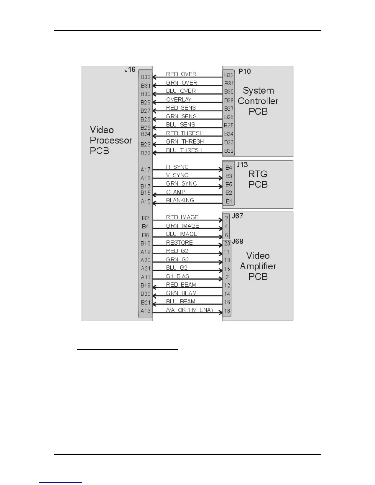
Figure 5-8
Video Processor PCB I/O diagram for PCBs.
Video Processor PCB - Outputs
RGB_VID - red, green, or blue video signal to Video Amplifier PCB, typically 0-
1 V.
H&V_SYNC - horizontal sync pulse goes to the Raster Timing Generator PCB.
GRN_SYNC - sync-on-green sync pulse goes to the Raster Timing Generator
PCB.
RESTORE - DC Restore control signal to the Video Amplifier PCB. This signal
controls the DC level of the image signal, clamping it to the proper level on the
Video Amplifier PCB.
 Loading...