Chapter 7---Troubleshooting
Model 250 Service Manual 7-15
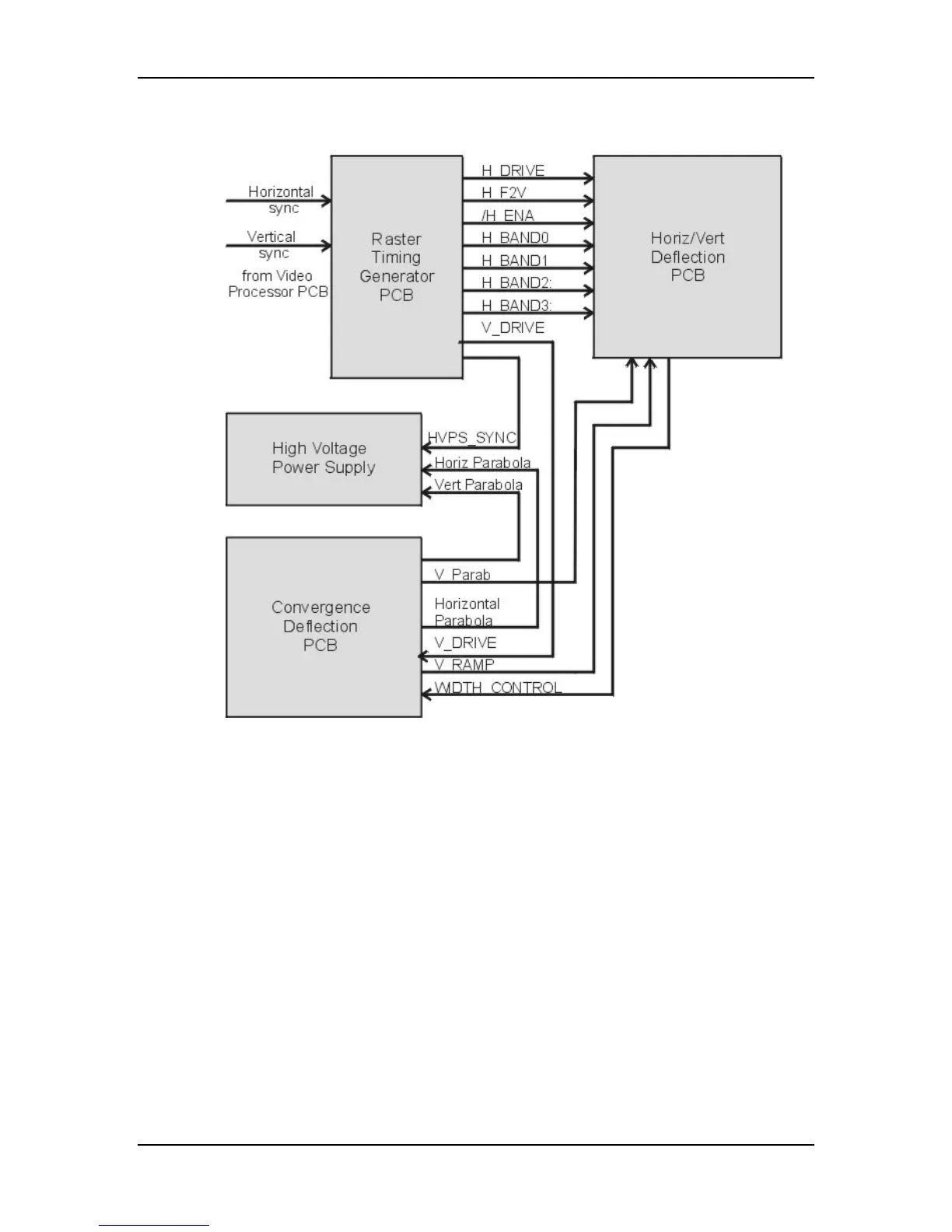
Deflection Path
Figure 7-12
CRT Deflection path from Raster Timing Generator PCB.
The Raster Timing Generator PCB receives the horizontal and vertical sync
pulses from the Video Processor PCB, and uses a Phase Locked Loop circuit to
lock to the horizontal sync. It sends a sample of the horizontal frequency
(H_DRIVE) to the Horizontal Vertical Deflection PCB to set the timing of the
Horizontal Amplifier, a Switched Mode Power Supply that generates the
horizontal deflection sawtooth waveform. The Raster Timing Generator PCB
divides the range of horizontal scan frequencies into four groups or bands because
the retrace or flyback timing varies dramatically from the lowest frequency (15
kHz) to the highest frequency (90 kHz).
The Horizontal Vertical Deflection PCB generates the horizontal waveforms that
drive the CRT Yokes. Many of the geometric corrections are integrated into the
horizontal waveform at the Horizontal Vertical Deflection PCB such as
Pincushion, Keystone, Skew, and Bow. The vertical size is be adjusted on the
Horizontal Vertical Deflection PCB.
 Loading...