Adjusting the Digital Video Cassette Camera with JVC Service Support System Software
69
7.
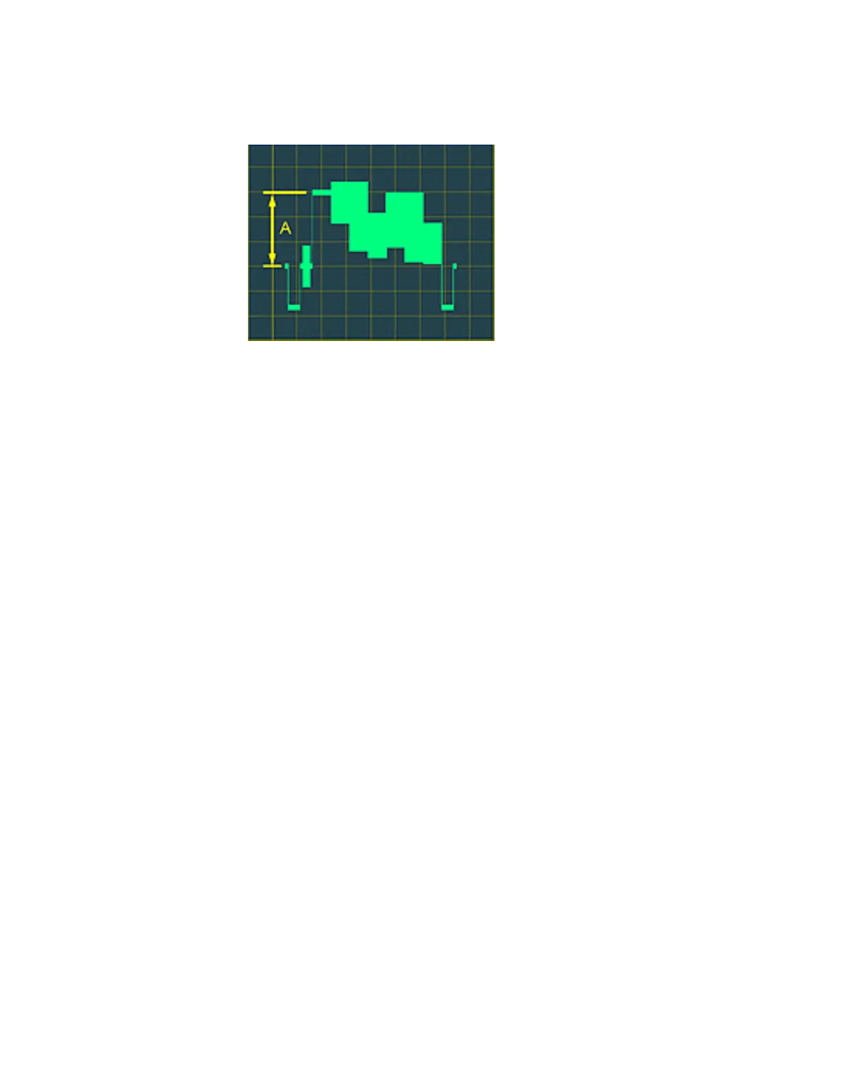
Click the Up and Down Arrows to adjust the amplitude of the signal so that
the white bar to the blanking level is 0.65 V p to p.
Figure 110 Set the Amplitude of the White Bar
8. Notice that the Editing window has several tabs. Some of the tabs may not
be visible. You can view hidden tabs by clicking the Left and Right Arrows
located to the right of the tabs.
9. Select the tab next to the Iris PWM tab, labeled 110h in this example, by
clicking it. View the video output signal using a vectorscope. Click the Up
and Down Arrows to alter the vector waveform. Notice that the waveform
varies along the y axis of the vector display.
10. Select the next tab, labeled 111h in this example, by clicking it. Click the
Up and Down Arrows in the Editing window. Notice that the waveform
varies along the x axis of the vector display.
11. Select the next tab, labeled 116h in this example. Click the Up and Down
Arrows in the Editing window. Notice that the y axis of the waveform
rotates.
12. Select the next tab, labeled 117h in this example. Click the Up and Down
Arrows in the Editing window. Notice that the x axis of the waveform
rotates.