Adjusting the Digital Video Cassette Camera with JVC Service Support System Software
73
GR-DVF11U, GR-DVF21U, GR-DVF31U
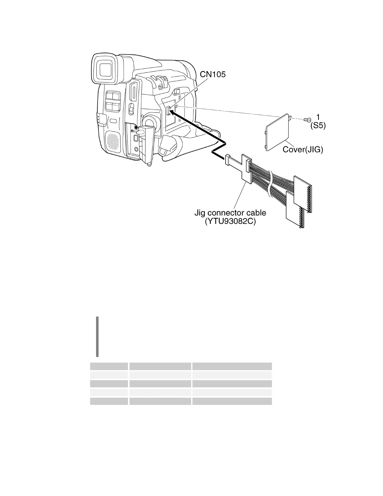
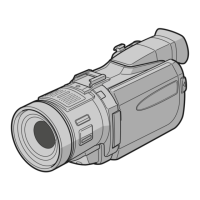
Figure 113 GR-DVF11U Adjustment Preparation
Adjustment preparation:
1. Remove the screw.
2. Remove the Jig Cover.
3. Connect the Jig Connector, P/N YTU93082C, to CN105 on the circuit
board.
The Jig Connector has two sets of test points. Use the set on the board marked
with the number 14 on it.
The pin numbers specified in the adjustment procedures are for connector
CN105, not for the Jig Connector, YTU93082C. Use the table to determine the
Jig Connector pin number.
Mnemonic CN105 Pin Number Jig Connector Pin Number
Main VCO 19 7
FS PLL 3 4
REC MON 17 3
HID 20 9
Table 8 Jig Connector YTU93082C Pin-out