2-13
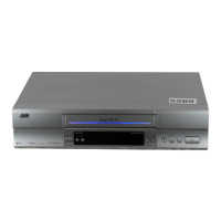
2.2.17 Take-up lever, take-up head and control plate
guide
(1) Remove the spring of the take-up lever from the main
deck.
(2) Remove the lug (A) of the take-up lever from the main
deck and pull out the take-up lever and the take-up head
together.
(3) Remove the screw (A).
(4) Align the idler arm assembly pin in the center (centre) of
the R section of the control plate guide, remove the con-
trol plate guide lugs (B) and (C) from the main deck, and
remove the control plate guide.
Fig. 2-2-17a
Take-up head
Screw(A)
Lug(A)
Lug(B)
Control plate guide
Take-up lever
Lug(C)
Idler arm assembly pin
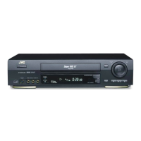
2.2.18 Capstan brake assembly
1. How to remove
(1) Move the lug (A) of the capstan brake assembly in the
arrow-indicated direction so that it comes into alignment
with the notch of the main deck. (See Fig. 2-2-18a.)
(2) Remove the lug (B) of the capstan brake assembly from
the main deck and remove the capstan brake assembly.
Fig. 2-2-18a
Capstan brake assembly
Lug(A)
Lug(B)
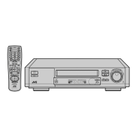
2.2.19 Sub brake assembly (take-up side)
1. How to remove
(1) Remove the spring attached to the lid guide and sub
brake assembly (take-up side).
(2) Bring the lug (A) of the sub brake assembly (take-up side)
into alignment with the notch of the main deck.
(3) Remove the lugs (B) and (C) of the sub brake assembly
(take-up side) from the main deck and remove the sub
brake assembly (take-up side).
Fig. 2-2-19a
Spring
Sub brake
assembly
(take-up side)
Lug(B)
Lug(A)
Lug(C)
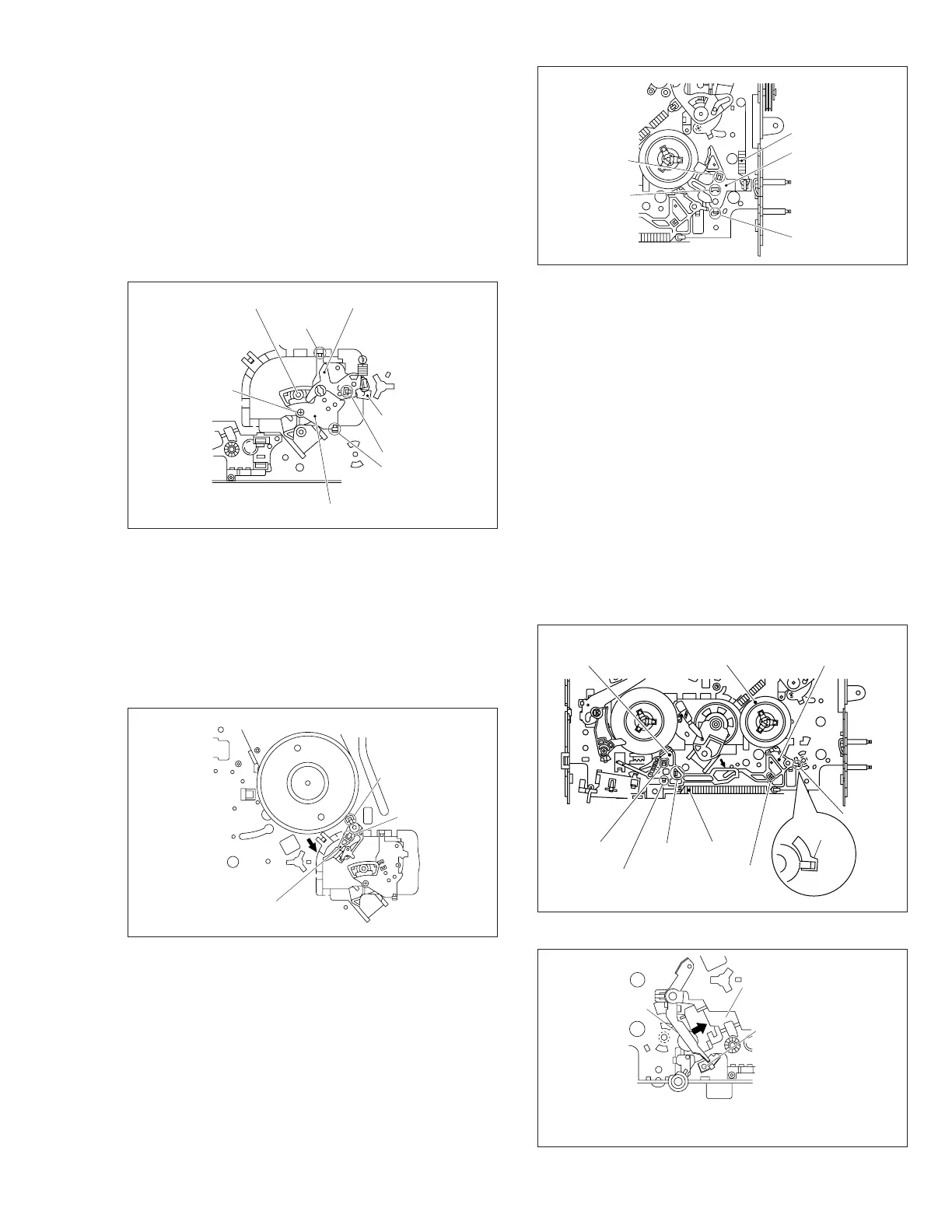
Fig. 2-2-20a
Lug(D)
Lug(C)
SpringLug(E)
Lug(A)
Lug(B)
Main brake assembly
(take-up side)
Reel disk
(take-up side)
Main brake assembly
(supply side)
Notch
2.2.20 Main brake assembly (take-up side), reel disk
(take-up side) and main brake assembly (supply
side)
1. How to remove
(1) Move the main brake assembly (take-up side) in the ar-
row-indicated direction and remove the reel disk (take-
up side).
(2)
Remove the spring attached to the main brake assembly.
(3) Remove the lug (A) of the main brake assembly (take-
up side) and pull out the lug (B) after bringing it into align-
ment with the main deck notch.
(4) Remove the lugs (C), (D) and (E) of the main brake as-
sembly (supply side) from the main deck and pull them
off. (See Fig.2-2-20a.)
(5) When installing the main brake assembly (take-up side),
slide the brake lever in the direction as indicated by the
arrow to prevent it from hitting the projection of the main
brake assembly (take-up side). (See Fig.2-2-20b.)
Fig. 2-2-20b
Projection of the main
brake assembly
(take-up side)
Rotary encoder guide
(
*
1)
Brake
lever
Note:
• The parts with marked (
*
) have different types of mechanisms (standard type
or high-speed FF/REW type).
*
1 : Uses the standard type mechanism only.
 Loading...