1-1
SECTION 1
DISASSEMBLY
1.1 HOW TO REMOVE THE MAJOR PARTS
1.1.1 Introduction
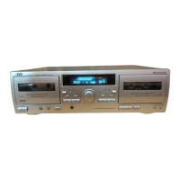
This set is a double-deck video recorder integrating a Mini DV
deck and a VHS deck. Its internal structure is divided into three
sections that include the power supply, VHS and DV sections.
Therefore, the removal of major parts will also be described
under three separate sections as listed below.
1. COMMON section
2. VHS section
3. DV section
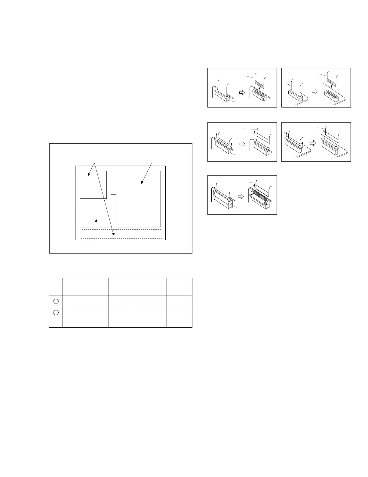
1.2 HOW TO READ THE DISASSEMBLY AND ASSEMBLY
3. DV section
1. COMMON section
2. VHS section
< TOP VIEW >
(1) Order of steps in Procedure
When reassembling, perform the step(s) in the reverse order.
These numbers are also used as the identification (location) No.
of parts Figures.
(2) Part name to be removed or installed.
(3) Fig. No. showing procedure or part location.
(4) Identification of part to be removed, unhooked, unlocked,
released, unplugged, unclamped or unsoldered.
P= Spring, W= Washer, S= Screw, L= Locking tab, SD= Solder,
CN**(WR**)= Remove the wire (WR**) from the connector
(CN**).
Note:
• The bracketed ( ) WR of the connector symbol are as-
signed nos. in priority order and do not correspond to
those on the spare parts list.
(5) Adjustment information for installation
Fig. 1-1-1
§§ §§ §
(1) (2) (3) (4) (5)
Step/
Loc No.
Fig. No.
Point NotePart name
Top cover, Bracket COM1
4(S1), 3(S2), 2(L1), (L2)
2(S3)
1
—
Front panel
assembly
COM2 8(L3),
CN7507(WR1),
CN3011(WR2)
<Note
1,2,3,4>
2
1.3 DISCONNECTION OF CONNECTORS (WIRES)
CONNECTOR
FPC
CONNECTOR
FPC
Fig. 1-3-1 Fig. 1-3-2
Fig. 1-3-3 Fig. 1-3-4
CONNECTOR
FPC
Fig. 1-3-5
CONNECTOR
FPC
CONNECTOR
FPC
 Loading...