B . c y l i n d e r h e a d i n s t a l l a t i o n
REMOVAL
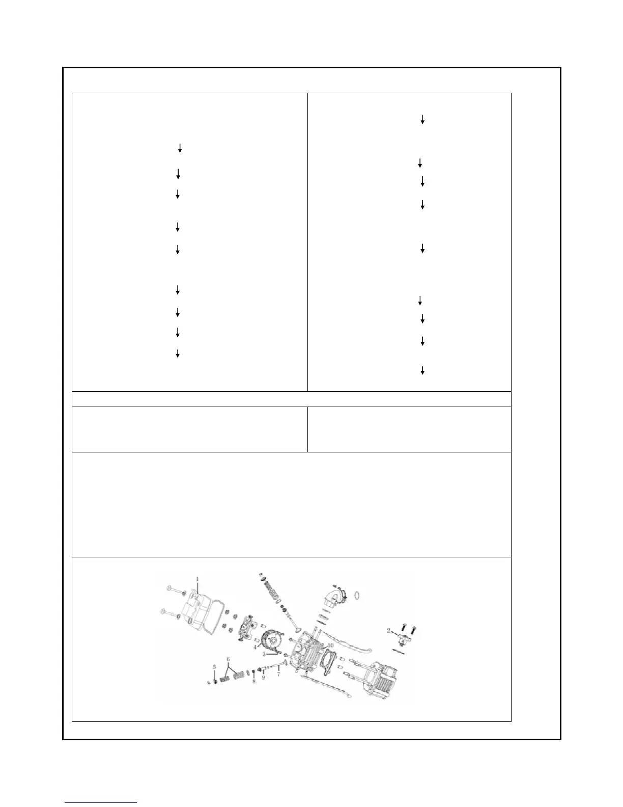
Cylinder head cover (1)/cylinder head cover seal bar
Right against “T” mark on magneto
(in the bottom of exhaust stroke )
timing chain tensioner(2)
atmolysis shaft assy.(3)/atmolysis shaft chain
(4)
(shuf off)
Atmolysis shaft holder assy./Atmolysis shaft fixer assy.
Cylinder head assy.
valve lock clip/valve spring holder(5)/inlet、exhaust
valve spring)
(special tool T04)
inlet valve and exhaust valve(7)
Valve oil seal assy.(8)
Valve pipe(9)
Cylinder head(10)
Installation
Cylinder head
Valve pipe/valve oil seal assy./gasket
Inlet valve and exhaust valve/valve
spring/spring holder/lock clip
Cylinder head assy.
Atmolysis shaft chain/atmolysis shaft
assy.
(mesh)
Atmolysis shaft assy. and atmolysis shaft
fixer assy.
Right against mark “T” on magneto and
correct timing mark on timing gears
(keep timing scale of timing gears on the
same level with joint surface of cylinder
head cover)
Timing chain tensioner(adjust)
Adjust valve clearance
(inlet valve clearance: 0.03~0.05mm,
exhaust valve clearance: 0.05~0.06mm)
Cylinder head cover and seal rubber bar
*Remove it if necessary
TORQUE:
::
:
1. Cylinder head cover fixing bolt 10~12N·M
2. Tension bolt and fixing bolt 10~12 N·M
3. Cam fixer locknut 22~25 N·M
4. Inlet pipe locknut 10~12 N·M
NOTICE:
::
:
1.Skive valve before installing vavle, and shake it, valve and valve seat should be even after
skiving.
2. Daub valve lever with some cream to avoid scratch it, after having installing it, valve lever
should be turned flexibly without block.
3. Be sure to keep dense end of valve spring down
 Loading...