13-14 Performance Verification
500mA range readback accuracy
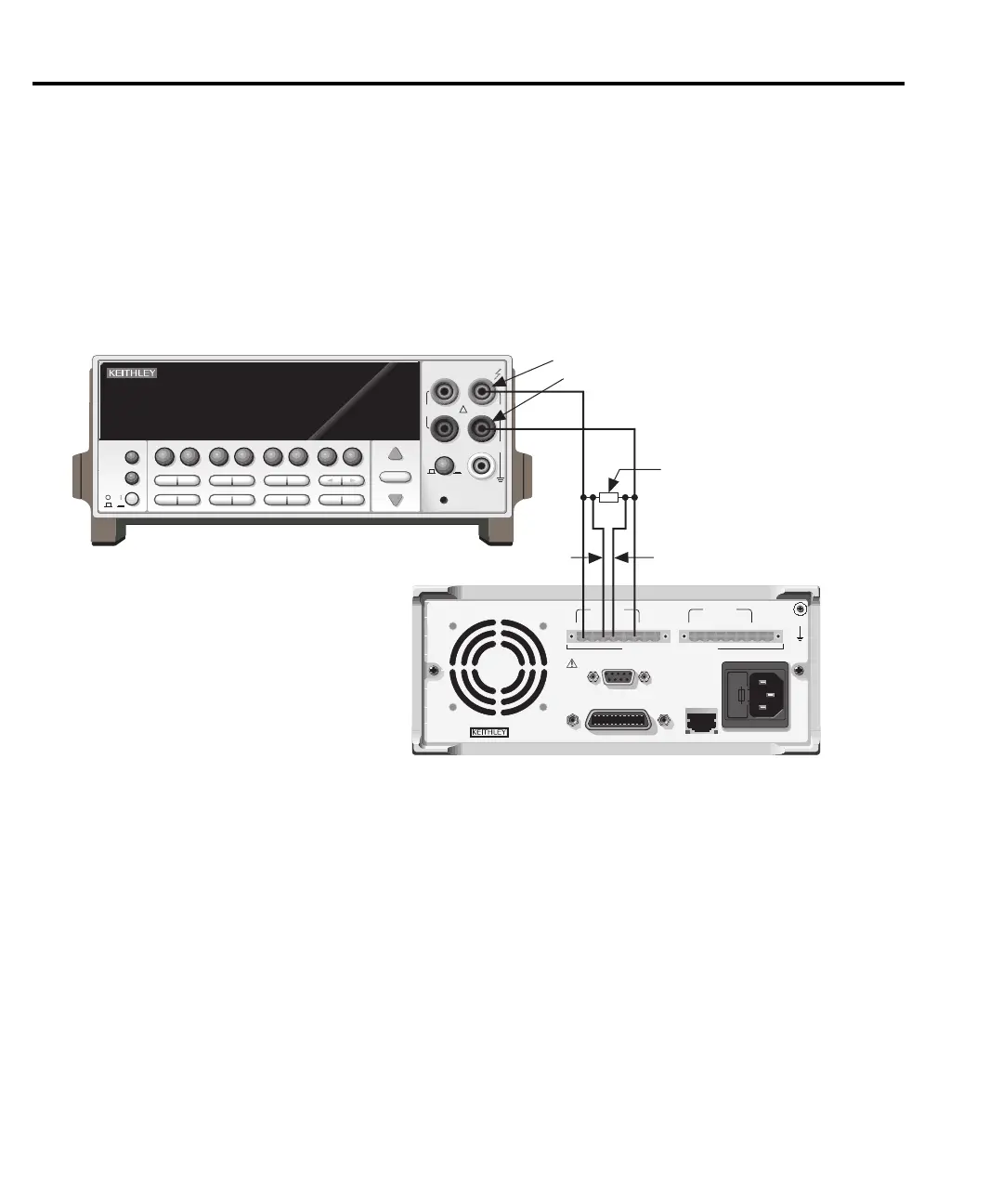
1. With the power supply’s output off, connect the digital multimeter and characterized
30Ω resistor to the Model 2306-PJ OUTPUT #1 terminals, as shown in Figure 13-4. Be
sure to observe proper polarity and connections (30Ω
resistor between SOURCE + and
DMM INPUT HI; SOURCE - to DMM INPUT LO).
Figure 13-4
Connections for 500mA current verification tests
WARNING:
NO INTERNAL OPERATOR SERVICABLE PARTS,SERVICE BY QUALIFIED PERSONNEL ONLY.
CAUTION:
FOR CONTINUED PROTECTION AGAINST FIRE HAZARD,REPLACE FUSE WITH SAME TYPE AND RATING.
MADE IN
U.S.A.
LINE RATING
100-120VAC, 200-240VAC
50, 60 HZ 165VA MAX
LINE FUSE
SLOWBLOW
2.0A, 250V
IEEE-488
(ENTER IEEE ADDRESS
FROM FRONT PANEL MENU)
REMOTE
DISPLAY
OPTION
+++
____
+
SOURCE SENSE
DVM IN
SOURCE
OUTPUT #1
ISOLATION FROM EARTH: 22 VOLTS MAX.
RELAY
CONTROL
24VDC MAX
CAT I
DVM IN
+30 VDC MAX
+++
____
+
SOURCE SENSE
DVM IN
SOURCE
OUTPUT #2
NEXT
PREV
POWER
DISPLAY
2001 MULTIMETER
DCV ACV DCI ACI •2 •4
FREQ TEMP
REL TRIG
INFO LOCAL EXIT ENTER
RANGE
RANGE
!
FR
500V
PEAK
FRONT/REAR
2A 250V
AMPS
CAL
STORE RECALL
CHAN SCAN
FILTER MATH
CONFIG MENU
HI
INPUT
LO
SENSE
• 4 WIRE
INPUTS
350V
PEAK
1100V
PEAK
AUTO
Model 2001 DMM
Model 2306-PJ
Input LO
Input HI
Source + Source -
30 Ω Resistor
Note: Use 4-wire connections
to resistor terminals.
Sense -Sense +
OUTPUT #1 connections
shown. Use OUTPUT #2
for Charger Channel.
Test Equipment Depot - 800.517.8431 - 99 Washington Street Melrose, MA 02176
TestEquipmentDepot.com

 Loading...


