1-6 Getting Started
NOTE When using the power supply as a sink (negative polarity), the power supply is dissi-
pating rather than sourcing power (see “Sink Operation” in Section 2).
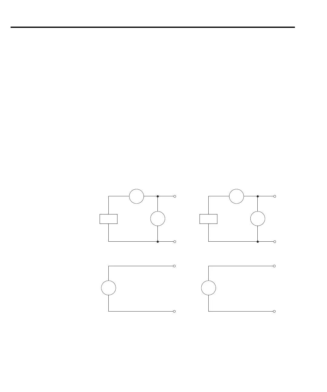
A simplified diagram of the power supply is shown in Figure 1
-3. Note that it can read back
the output voltage (V
meter
) and current (I
meter
). Display resolution for voltage readback is 1mV.
Current Readback Range: The Model 2306 has two ranges for current readback: 5A and
5mA. On the 5A
range display resolution is 100μA, and on the 5mA range resolution is 0.1μA.
The power supply also has a digital voltmeter (DVM) that is independent of the power supply
circuit.
The DVM can measure up to +30V (1mV resolution).
When used with a pulsed load, the power supply can read back peak current, idle current, and
a
verage current. See Section 3 for details. A long integration (up to 60 seconds) function is
provided to measure average current of a low frequency pulse (long period) or a series of pulses.
See Section 4 for details.
Battery Channel
(Channel #1)
Source
+
_
V-Source
with I-Limit
I meter
V meter
+
_
Digital
Voltmeter
DVM
Charger Channel
(Channel #2)
Source
+
_
V-Source
with I-Limit
I meter
V meter
+
_
Digital
Voltmeter
DVM
igure 1-3
Simplified power supply diagram
Test Equipment Depot - 800.517.8431 - 99 Washington Street Melrose, MA 02176
TestEquipmentDepot.com

 Loading...


