4-8
n
COMPONENT ACCESS
Ice Maker Top Components (cont.)
6. Lay the control housing on the board and blanket
previously positioned. While supporting top remove the
ground wire. See Figure 23.
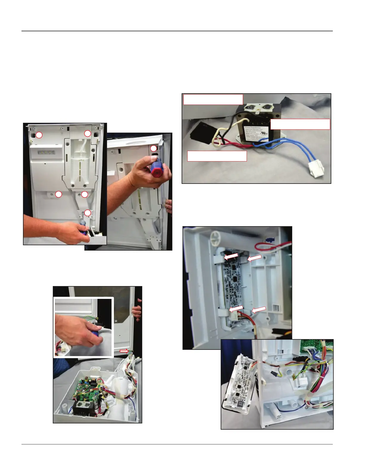
REMOVING USER INTERFACE BOARD
8. Release retainers to remove UI board. See Figure 25.
FIGURE 23
t,/Z>WKK>KZWKZd/KE KE&/Ed/> ϮϮ
Zz^d>ϱϬη/D,/EͲϮϬϭϯdϯ
^^/E'KEdZK>KDWZdDEd
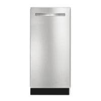
REMOVING TRANSFORMER
7. Remove 2 screws and connectors.
NOTE: The transformer doesn’t have to be removed to
make voltage and resistance checks. See Figure 24.
FIGURE 24
t,/Z>WKK>KZWKZd/KE KE&/Ed/> Ϯϯ
dZE^&KZDZ
Zz^d>ϱϬη/D,/EͲϮϬϭϯdϯ
ZĞĚZĞĚϭϮϴs
>ĞƐƐƚŚĂŶϮK,D^ZĞƐŝƐƚĂŶĐĞ
ůƵĞůƵĞϵϰs
>ĞƐƐƚŚĂŶϮK,D^ZĞƐŝƐƚĂŶĐĞ
ůĂĐŬtŚŝƚĞϭϮϬs
ϰK,D^ZĞƐŝƐƚĂŶĐĞ
t,/Z>WKK>KZWKZd/KE KE&/Ed/> Ϯϰ
h^Z/EdZ&KZZDKs>
Zz^d>ϱϬη/D,/EͲϮϬϭϯdϯ
t,/Z>WKK>KZWKZd/KE KE&/Ed/> Ϯϰ
h^Z/EdZ&KZZDKs>
Zz^d>ϱϬη/D,/EͲϮϬϭϯdϯ
FIGURE 25
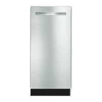
ACCESSING THE CONTROL COMPARTMENT
NOTE: This procedure will prove challenging the rst time
attempted.
5. 5 hex head screws will need to be removed while
supporting the top. Grasp the center of the top with left
hand to support top. Screw # 5 needs to be the last to
be removed. When the last screw is removed the control
housing will separate from the top. See Figure 22.
FIGURE 22
t,/Z>WKK>KZWKZd/KE KE&/Ed/>
Ϯϭ
^^/E'KEdZK>KDWZdDEd
Zz^d>ϱϬη/D,/EͲϮϬϭϯdϯ
ϯ
ϰ
ϱ
Ϯ
ϭ
ϱ
t,/Z>WKK>KZWKZd/KE KE&/Ed/>
Ϯϭ
^^/E'KEdZK>KDWZdDEd
Zz^d>ϱϬη/D,/EͲϮϬϭϯdϯ
ϯ
ϰ
ϱ
Ϯ
ϭ
 Loading...