Inspection and Service
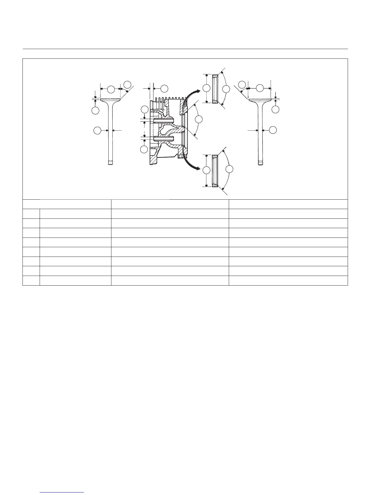
Valve Details
A
A
A
B
B
C
D
D
E
E
F F
G
G
H
H
EXHAUST VALVE
INTAKE VALVE
INTAKE
INSERT
EXHAUST
INSERT
Dimension Intake Exhaust
A Seat Angle 89° 89°
B Insert O.D. 36.987/37.013 mm (1.4562/1.4572 in.) 32.987/33.013 mm (1.2987/1.2997 in.)
C Guide Depth 4 mm (0.1575 in.) 4 mm (0.1575 in.)
D Guide I.D. 7.038/7.058 mm (0.2771/0.2779 in.) 7.038/7.058 mm (0.2771/0.2779 in.)
E Valve Head Diameter 33.37/33.63 mm (1.3138/1.3240 in.) 29.37/29.63 mm (1.1563/1.1665 in.)
F Valve Face Angle 45° 45°
G Valve Margin (Min.) 1.5 mm (0.0591 in.) 6.982/7.000 mm 1.5 mm (0.0591 in.)
H Valve Stem Diameter (0.2749/0.2756 in.) 6.970/6.988 mm (0.2744/0.2751 in.)
After cleaning, check fl atness of cylinder head and
corresponding top surface of crankcase, using a surface
plate or piece of glass and feeler gauge. Maximum
allowable out of fl atness is 0.076 mm (0.003 in.).
Carefully inspect valve mechanism parts. Inspect valve
springs and related hardware for excessive wear or
distortion. Check valves and valve seat area or inserts
for evidence of deep pitting, cracks, or distortion. Check
clearance of valve stems in guides. See valve details
and specifi cations.
Hard starting or loss of power accompanied by high
fuel consumption may be symptoms of faulty valves.
Although these symptoms could also be attributed to
worn rings, remove and check valves fi rst. After removal,
clean valve heads, faces, and stems with a power wire
brush. Then, carefully inspect each valve for defects
such as a warped head, excessive corrosion, or a worn
stem end. Replace valves found to be in bad condition.
Valve Guides
If a valve guide is worn beyond specifi cations, it will not
guide valve in a straight line. This may result in burnt
valve faces or seats, loss of compression, and excessive
oil consumption.
To check valve guide-to-valve stem clearance,
thoroughly clean valve guide and, using a split-ball
gauge, measure inside diameter of guide. Then, using
an outside micrometer, measure diameter of valve stem
at several points on stem where it moves in valve guide.
Use largest stem diameter to calculate clearance by
subtracting stem diameter from guide diameter. If intake
clearance exceeds 0.038/0.076 mm (0.0015/0.0030
in.) or exhaust clearance exceeds 0.050/0.088 mm
(0.0020/0.0035 in.), determine whether valve stem or
guide is responsible for excessive clearance.
Maximum (I.D.) wear on intake valve guide is 7.134 mm
(0.2809 in.) while 7.159 mm (0.2819 in.) is maximum
allowed on exhaust guide. Guides are not removable
but can be reamed 0.25 mm (0.010 in.) oversize. Valves
with 0.25 mm oversize stems must then be used.
If guides are within limits but valve stems are worn
beyond limits, install new valves.
Disassembly/Inspection and Service
112 24 690 01 Rev. KKohlerEngines.com

 Loading...