EFI SYSTEM-BOSCH
64
24 690 01 Rev. KKohlerEngines.com
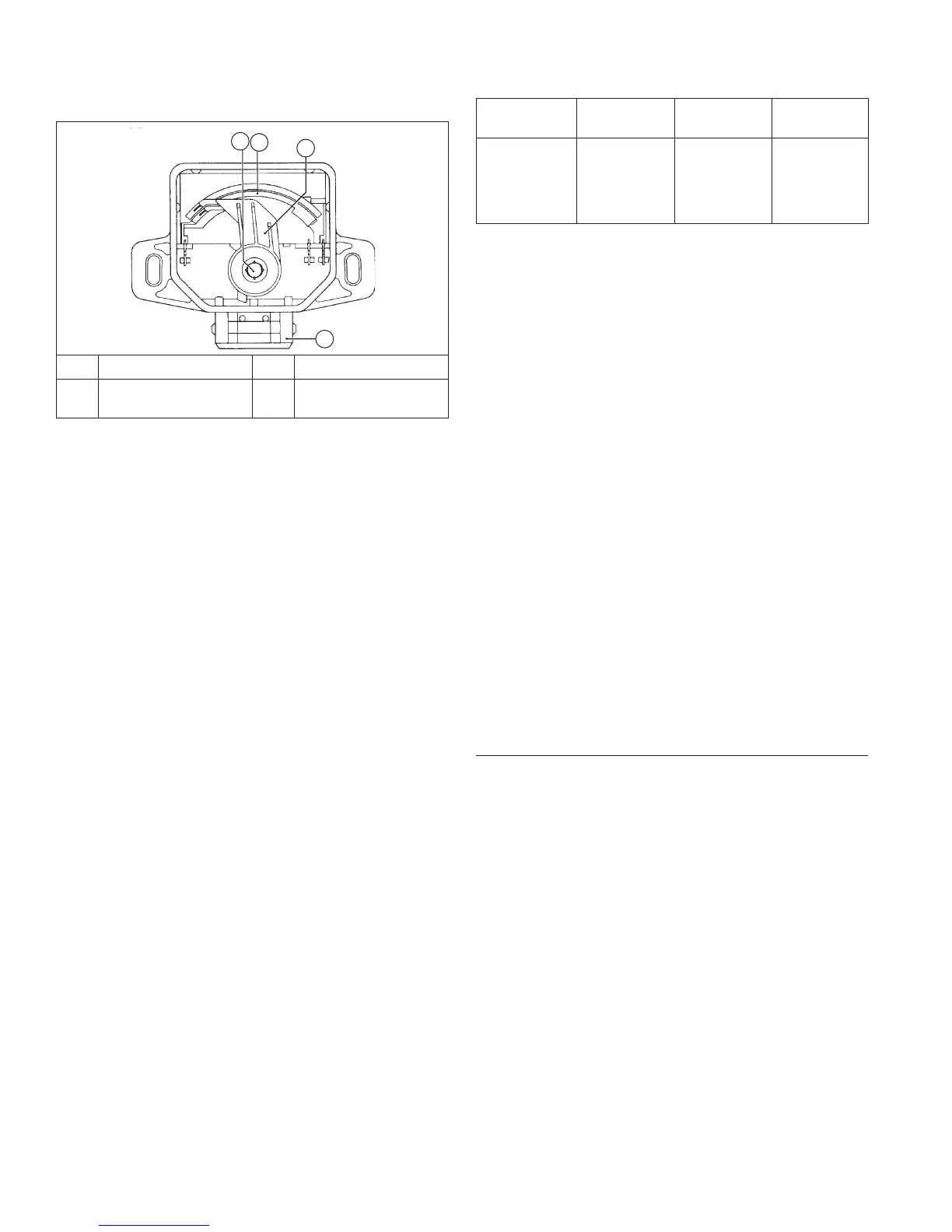
Throttle Position Sensor (TPS)
A
C
B
D
A Throttle Valve Shaft B Resistor Track
C
Wiper Arm with
Wiper
D
Electrical
Connection
The TPS is a sealed, non-serviceable assembly. If
diagnosis indicates a bad sensor, complete replacement
is necessary. If a blink code indicates a problem with
TPS, it can be tested as follows:
1. Counting number of turns, back out idle speed
adjusting screw (counterclockwise) until throttle
plates can be closed completely.
2. Disconnect main harness connector from ECU, but
leave TPS mounted to throttle body/manifold.
3. Connect ohmmeter leads as follows:
(See chart on pages).
“35 Pin” (MA 1.7) Metal-Cased ECU: Red
(positive) ohmmeter lead to #12 pin terminal, and
Black (negative) ohmmeter lead to #27 pin
terminal.
“24 Pin” (MSE 1.0) Plastic-Cased ECU: Red
(positive) ohmmeter lead to #8 pin terminal, and
Black (negative) ohmmeter lead to #4 pin
terminal.
“32 Pin” (MSE 1.1) Plastic-Cased ECU: Red
(positive) ohmmeter lead to #8 pin terminal, and
Black (negative) ohmmeter lead to #4 pin
terminal.
Hold throttle closed and check resistance. It should be
800-1200 Ω.
4. Leave leads connected to pin terminals as described
in step 3. Rotate throttle shaft slowly
counterclockwise to full throttle position. Monitor dial
during rotation for indication of any momentary short
or open circuits. Note resistance at full throttle
position. It should be 1800-3000 Ω.
5. Disconnect main wiring harness connector from
TPS, leaving TPS assembled to manifold. Refer to
chart below and perform resistance checks indicated
between terminals in TPS switch, with throttle in
positions specifi ed.
Throttle
Position
Between
Terminals
Resistance
Value (Ω)
Continuity
Closed
Closed
Full
Full
Any
2 & 3
1 & 3
2 & 3
1 & 3
1 & 2
800-1200
1800-3000
1800-3000
800-1200
1600-2500
Yes
Yes
Yes
Yes
Yes
If resistance values in steps 3, 4, and 5 are within
specifi cations, go to step 6.
If resistance values are not within specifi cations,
or a momentary short or open circuit was
detected during rotation (step 4), TPS needs to
be replaced, go to step 7.
6. Check TPS circuits (input, ground) between TPS
plug and main harness connector for continuity,
damage, etc. See chart on pages
“35 Pin” (MA 1.7) Metal-Cased ECU: Pin
Circuits #12 and #27.
“24 Pin” (MSE 1.0) Plastic-Cased ECU: Pin
Circuits #8 and #4.
“32 Pin” (MSE 1.1) Plastic-Cased ECU: Pin
Circuits #8 and #4.
a. Repair or replace as required.
b. Turn idle speed screw back in to its original
setting.
c. Reconnect connector plugs, start engine and
retest system operation.
7. Remove two mounting screws from TPS. Save
screws for reuse. Remove and discard faulty TPS.
Install replacement TPS and secure with original
mounting screws.
a. Reconnect both connector plugs.
b. Perform appropriate “TPS Initialization
Procedure” integrating new sensor to ECU.
TPS Initialization Procedure
For“35 Pin” (MA 1.7) Metal-Cased ECU and“24 Pin”
(MSE 1.0) Plastic-Cased ECU only
1. Check that basic engine, all sensors, fuel, fuel
pressure, and battery are good and functionally
within specifi cations.
Important!
2. Remove/disconnect ALL external loads from engine
(belts, pumps, electric PTO clutch, alternator,
rectifi er-regulator, etc.).
3. Start engine and allow it to warm up for 5-10
minutes, so oil temperature is above 55°C (130°F).
4. Move throttle control to idle position and allow
engine to stabilize for a minimum of one minute.
5. Install a heavy rubber band around throttle lever and
manifold boss, to fi rmly hold throttle against idle
stop. On some EFI engines there is a dampening
spring on end of idle speed screw. Dampening
spring (if used) should be fully compressed and tab
on throttle lever in direct contact with speed screw.
Adjust idle speed to 1500 RPM, using a tachometer.
6. Shut off engine.

 Loading...