Valve Stem Seals
These engines use valve stem seals on intake valves
and on exhaust valves. Always use a new seal whenever
valve is removed or if seal is deteriorated or damaged in
any way. Never reuse an old seal.
Assemble Cylinder Heads
Prior to installation, lubricate all components with engine
oil, paying particular attention to lip of valve stem seal,
valve stems, and valve guides. Install following items in
order listed below using a valve spring compressor.
• Intake and exhaust valves.
• Valve spring retainers.
• Valve springs.
• Valve spring caps.
• Valve spring keepers.
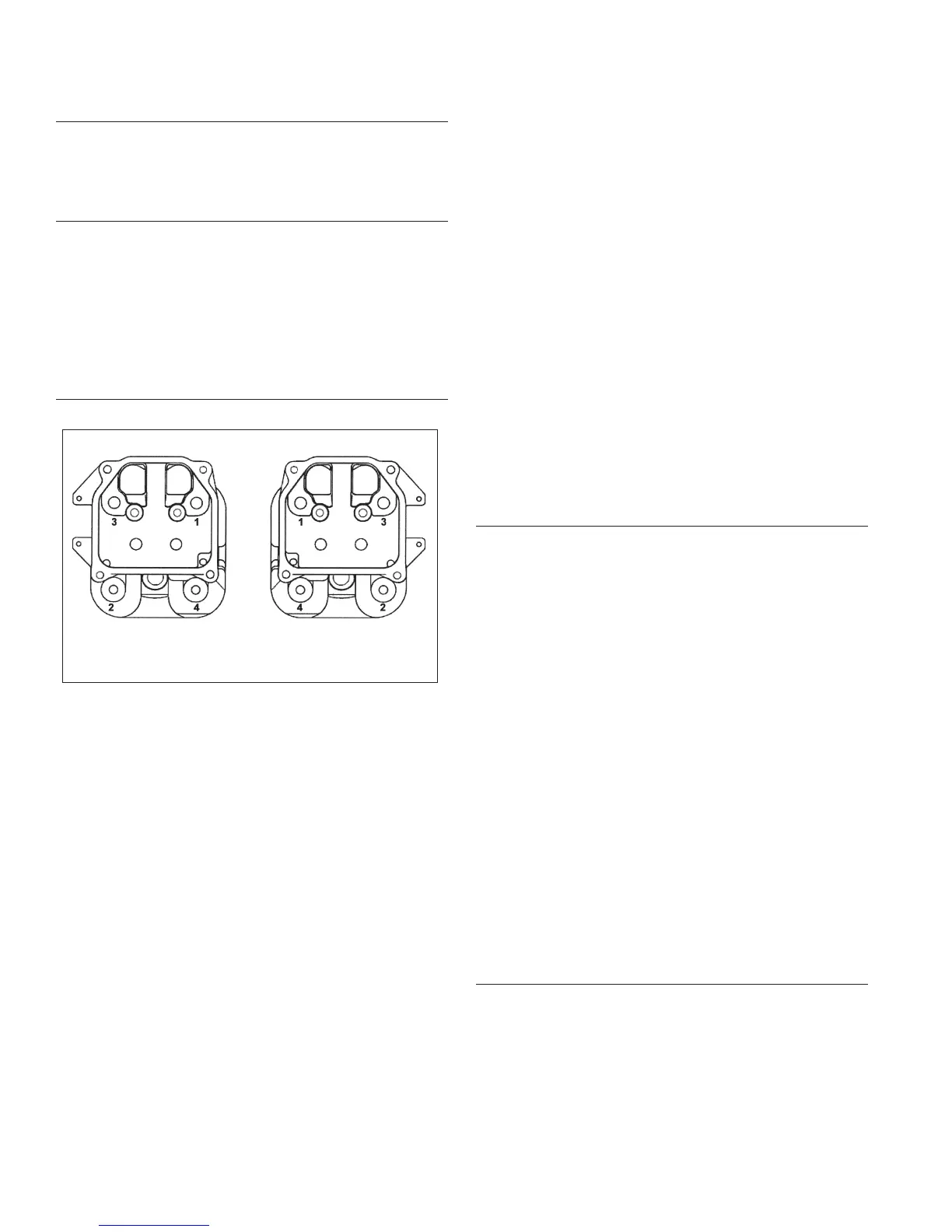
Install Cylinder Heads
Torque Sequence
#1 #2
NOTE: Cylinder heads must be attached with original
type of mounting hardware, using either screws,
or mounting studs with nuts and washers. Do
not intermix components.
NOTE: Match numbers embossed on cylinder heads
and crankcase.
1. Check to make sure there are no nicks or burrs on
sealing surfaces of cylinder head or crankcase.
Heads secured with mounting studs, nuts, and
washers:
2. If all studs were left intact, go to Step 6. If any studs
were disturbed or removed, install new studs as
described in Step 3. Do not use/reinstall any
loosened or removed studs.
3. Install new mounting stud(s) into crankcase.
a. Thread and lock 2 mounting nuts together on
smaller diameter threads.
b. Thread opposite end of stud with preapplied
locking compound into crankcase until specifi ed
height from crankcase surface is achieved. When
threading in studs, use a steady tightening motion
without interruption until proper height is
obtained. Otherwise, frictional heat from engaging
threads may cause locking compound to set up
prematurely.
Studs closest to lifters must have an exposed height of
75 mm (2 15/16 in.).
Studs furthest from lifters must have an exposed height
of 69 mm (2 3/4 in.).
c. Remove nuts and repeat procedure as required.
4. Check dowel pins are in place and install a new
cylinder head gasket (part number facing up).
5. Install cylinder head. Match numbers on cylinder
heads and crankcase. Make sure head is fl at on
gasket and dowel pins.
6. Lightly lubricate exposed (upper) threads of studs
with engine oil. Install a fl at washer and hex nut onto
each mounting stud. Torque hex nuts in 2 stages;
fi rst to 16.9 N·m (150 in. lb.), fi nally to 33.9 N·m (300
in. lb.). Follow torque sequence.
Heads secured with screws:
2. Install a new cylinder head gasket, (part number
facing up).
3. Install cylinder head and start screws.
4. Torque screws in 2 stages; fi rst to 22.6 N·m (200 in.
lb.), fi nally to 41.8 N·m (370 in. lb.). Follow torque
sequence.
Install Push Rods and Rocker Arms
NOTE: Push rods should always be installed in same
position as before disassembly.
1. Note mark or tag identifying push rod as either
intake or exhaust and cylinder #1 or #2. Dip ends of
push rods in engine oil and install, making sure each
push rod ball seats in its hydraulic lifter socket.
2. Apply grease to contact surfaces of rocker arms and
rocker arm pivots. Install rocker arms and rocker arm
pivots on 1 cylinder head, and start screws.
3. Torque screws to 18.1 N·m (160 in. lb.). Repeat for
other rocker arm.
4. Use a spanner wrench or rocker arm lifting tool (see
Tools and Aids) to lift rocker arms and position push
rods underneath.
5. Repeat above steps for remaining cylinder. Do not
interchange parts from cylinder heads.
6. Rotate crankshaft to check for free operation of
valve train. Check clearance between valve spring
coils at full lift. Minimum allowable clearance is 0.25
mm (0.010 in.).
Check Assembly
Important: Rotate crankshaft a minimum of 2 revolutions
to check longblock assembly and overall proper
operation.
Install Spark Plugs
1. Check gap using wire feeler gauge. Adjust gap to
0.76 mm (0.03 in.).
2. Install plug into cylinder head.
3. Torque plug to 27 N·m (20 ft. lb.).
Reassembly
128 24 690 01 Rev. KKohlerEngines.com

 Loading...