specifi c area of piston. Detonation generally occurs from
using low octane fuels.
Preignition or ignition of fuel charge before timed spark
can cause damage similar to detonation. Preignition
damage is often more severe than detonation damage.
Preignition is caused by a hot spot in combustion
chamber from sources such as glowing carbon deposits,
blocked cooling fi ns, an improperly seated valve, or
wrong spark plug(s).
Replacement pistons are available in STD bore size, and
in 0.25 mm (0.010 in.), and 0.50 mm (0.020 in.) oversize.
Replacement pistons include new piston ring sets and
new piston pins.
Replacement ring sets are also available separately
for STD, 0.25 mm (0.010 in.), and 0.50 mm (0.020 in.)
oversize pistons. Always use new piston rings when
installing pistons. Never use old rings.
Some important points to remember when servicing
piston rings:
Piston Style A
1. Cylinder bore must be de-glazed before service ring
sets are used.
2. If cylinder bore does not need re-boring and if old
piston is within wear limits and free of score or scuff
marks, old piston may be reused.
3. Remove old rings and clean up grooves. Never
reuse old rings.
4. Before installing new rings on piston, place top 2
rings, each in turn, in its running area in cylinder
bore and check end gap. Top and center
compression ring end gap clearance is 0.25/0.56
mm (0.010/0.022 in.) with maximum wear limit of
0.94 mm (0.037 in.).
5. After installing new compression (top and middle)
rings on piston, check side clearance. If side
clearance is greater than specifi ed, a new piston
must be used.
Model ECH630-749 engines: Top compression
ring-to-groove side clearance is 0.050/0.095 mm
(0.0019/0.0037 in.). Middle compression ring-to-
groove side clearance is 0.030/0.075 mm
(0.0012/0.00307 in.).
Model CH26, CH735, CH745 engines: Top
compression ring-to-groove side clearance is
0.025/0.048 mm (0.0010/0.0019 in.). Middle
compression ring-to-groove side clearance is
0.015/0.037 mm (0.0006/0.0015 in.).
Piston Style B
1. Cylinder bore must be de-glazed before service ring
sets are used.
2. If cylinder bore does not need re-boring and if old
piston is within wear limits and free of score or scuff
marks, old piston may be reused.
3. Remove old rings and clean up grooves. Never
reuse old rings.
4. Before installing new rings on piston, place top 2
rings, each in turn, in its running area in cylinder
bore and check end gap.
80 mm bore engines: Top compression ring end gap
is 0.100/0.279 mm (0.0039/0.0110 in.). Middle
compression ring end gap is 1.400/1.679 mm
(0.0551/0.0661 in.).
83 mm bore engines: Top compression ring end gap
is 0.189/0.277 mm (0.0074/0.0109 in.). Middle
compression ring end gap is 1.519/1.797 mm
(0.0598/0.0708 in.).
5. After installing new compression (top and middle)
rings on piston, make sure ring-to-groove side
clearance is 0.030/0.070 mm (0.001/0.0026 in.). If
side clearance is greater than specifi ed, a new
piston must be used.
Install New Piston Rings
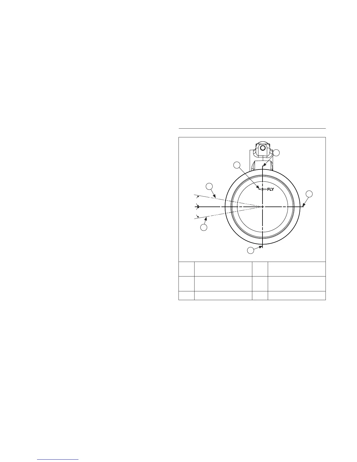
Piston Ring Orientation
10°
10°
F
A
B
C
D
E
A
Top Oil Ring Rail
Gap
B
Bottom Oil Ring Rail
Gap
C
Intermediate Ring
Gap
D
Oil Ring Expander
Gap
E Top Ring Gap F FLY Stamp
NOTE: Rings must be installed correctly. Ring
installation instructions are usually included with
new ring sets. Follow instructions carefully. Use
a piston ring expander to install rings. Install
bottom (oil control) ring fi rst and top
compression ring last.
To install new piston rings, proceed as follows:
1. Oil control ring (bottom groove): Install expander and
then rails. Make sure ends of expander are not
overlapped.
2. Middle compression ring (center groove): Install
center ring using a piston ring installation tool. Make
sure identifi cation mark is up or colored dye stripe
(if contained), is to left of end gap.
3. Top compression ring (top groove): Install top ring
using a piston ring expander. Make sure
identifi cation mark is up or colored dye stripe
(if contained), is to left of end gap.
Disassembly/Inspection and Service
118 24 690 01 Rev. KKohlerEngines.com

 Loading...