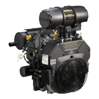
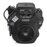
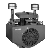
Lubrication System
9324 690 01 Rev. K KohlerEngines.com
CHANGE OIL AND FILTER
Change oil while engine is warm.
1. Clean area around oil fi ll cap/dipstick and drain plug.
Remove drain plug and oil fi ll cap/dipstick. Allow oil
to drain completely.
2. Clean area around oil fi lter. Place a container under
fi lter to catch any oil and remove fi lter. Wipe off
mounting surface. Reinstall drain plug. Torque to 10
ft. lb. (13.6 N·m).
3. Place new fi lter in shallow pan with open end up. Fill
with new oil until oil reaches bottom of threads. Allow
2 minutes for oil to be absorbed by fi lter material.
4. Apply a thin fi lm of clean oil to rubber gasket on new
fi lter.
5. Refer to instructions on oil fi lter for proper
installation.
6. Fill crankcase with new oil. Level should be at top of
indicator on dipstick.
7. Reinstall oil fi ll cap/dipstick and tighten securely.
8. Start engine; check for oil leaks. Stop engine; correct
leaks. Recheck oil level.
9. Dispose of used oil and fi lter in accordance with
local ordinances.
OIL COOLER (if equipped)
1. Clean fi ns with a brush or compressed air.
2. Remove screws securing oil cooler and tilt to clean
back side.
3. Reinstall oil cooler and torque to 2.2 N·m (20 in. lb.).
OIL SENTRY
™
(if equipped)
This switch is designed to prevent engine from starting
in a low oil or no oil condition. Oil Sentry
™
may not shut
down a running engine before damage occurs. In some
applications this switch may activate a warning signal.
Read your equipment manuals for more information.
Oil Sentry
™
pressure switch is installed in breather cover.
On engines not equipped with Oil Sentry
™
installation
hole is sealed with a 1/8-27 N.P.T.F. pipe plug.
Installation
1. Apply pipe sealant with Tefl on
®
(Loctite
®
PST
®
592™
Thread Sealant or equivalent) to threads of switch.
2. Install switch into tapped hole in breather cover.
3. Torque switch to 4.5 N·m (40 in. lb.).
Testing
Compressed air, a pressure regulator, pressure gauge,
and a continuity tester are required to test switch.
ECH Models:
Normally Closed Switch
1. Connect continuity tester across blade terminal and
metal case of switch. With 0 psi pressure applied to
switch, tester should indicate continuity (switch
closed).
2. Gradually increase pressure to switch. As pressure
increases through range of 2.0/5.0 psi, tester should
indicate a change to no continuity (switch open).
Switch should remain open as pressure is increased
to 90 psi maximum.
3. Gradually decrease pressure through range of
2.0/5.0 psi. Tester should indicate a change to
continuity (switch closed) down to 0 psi.
4. Replace switch if it does not operate as specifi ed.
Normally Open Switch
1. Connect continuity tester across blade terminal and
metal case of switch. With 0 psi pressure applied to
switch, tester should indicate no continuity (switch
open).
2. Gradually increase pressure to switch. As pressure
increases through range of 2.0/5.0 psi, tester should
indicate a change to continuity (switch closed).
Switch should remain closed as pressure is
increased to 90 psi maximum.
3. Gradually decrease pressure through range of
2.0/5.0 psi. Tester should indicate a change to no
continuity (switch open) down to 0 psi.
CH Models:
Pressure Switch PSI
12 099 04 2-6
24 099 03 2-5
25 099 27 2-5
28 099 01 2-6
48 099 07 12-16
52 099 08 7-11
52 099 09 7-11

 Loading...