METHOD FOR ADJUSTING TENSION OF CENTER BRACE
(Straight tilt dozer)
(Straight tilt power pitch dozer)
(Sigma dozer)
(Sigma power pitch dozer)
When transporting the machine, remove the whole set of the work equipment. When installing again, adjust the
tension of the center brace.
If the adjustment is not performed, the bushing at the mounting portion of the blade and straight frame comes
off, and soil and sand enter and cause premature wear or damage of the bushing. Adjust as follows.
WARNING
Except when operating the blade in step 4, always lock the blade control lever securely with the work
equipment lock lever.
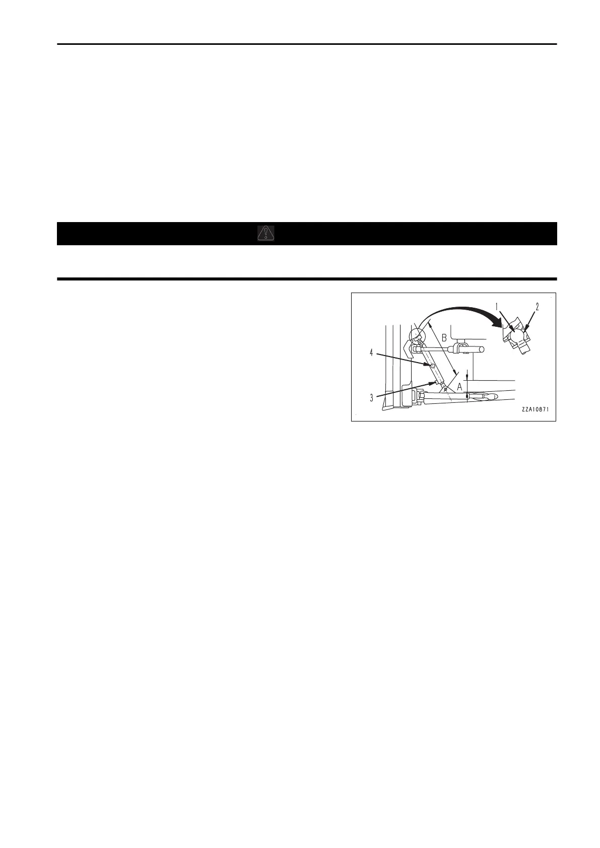
1.
Adjust with shim (2) so that the play of ball joint (1) is 0.2
to 0.7 mm (0.008 to 0.028 in).
For the adjustment method, see “METHOD FOR ADJUST-
ING SHIMS AT CENTER BRACE (4-49)”.
2.
Loosen bolt (3).
3.
Install the work equipment assembly.
4.
Operate the blade control lever to float the blade.
5.
Insert the bar in center brace hole (4) and turn the bar to
the protruding side.
Adjust clearance between the track shoe and frame (A) so
that it is equal on the right and left sides.
Rotating torque: 24.5 to 49 Nm {2.5 to 5 kgm, 18.1 to 36.2 lbft} (Blade at FLOAT)
Standard distance between the joints (B) is as shown below.
(D65EX)
Straight tilt dozer, straight tilt power pitch dozer: 995 mm (3 ft 3 in)
Sigma dozer, sigma power pitch dozer: 991 mm (3 ft 3 in)
(D65PX)
Straight tilt dozer, straight tilt power pitch dozer: 992 mm (3 ft 3 in)
(D65WX)
Sigma dozer, sigma power pitch dozer: 992 mm (3 ft 3 in)
6.
Tighten bolt (3).
Tightening torque: 490.3 to 608 Nm {50 to 62 kgm,362 to 448 lbft}
MAINTENANCE MAINTENANCE PROCEDURE
4-51

 Loading...