11-70
140-3 SERIES
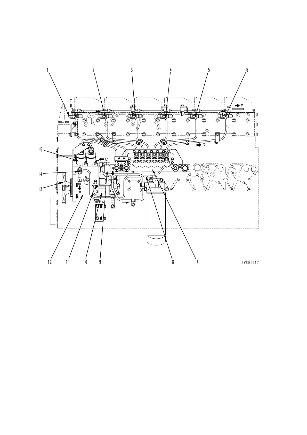
STRUCTURE AND FUNCTION, MAINTENANCE STANDARD FUEL PIPING
FUEL PIPING
★ The shape may differ according to the machine
model.
1.
Fuel injection pipe (No. 1 cylinder)
9.
Priming pump
2.
Fuel injection pipe (No. 2 cylinder)
10.
Feed pump
3.
Fuel injection pipe (No. 3 cylinder)
11.
Oil inlet pipe (for pump lubrication oil)
4.
Fuel injection pipe (No. 4 cylinder)
12.
High-pressure pump
5.
Fuel injection pipe (No. 5 cylinder)
13.
Fuel supply pump drive gear (No. of teeth: 48)
6.
Fuel injection pipe (No. 6 cylinder)
14.
Overflow valve
7.
Common rail
15.
PCV
8.
Fuel return pipe
 Loading...

