140-3 SERIES
12-21
TESTING AND ADJUSTING HANDLING CONTROLLER HIGH VOLTAGE CIRCUIT
HANDLING CONTROLLER HIGH VOLTAGE CIRCUIT
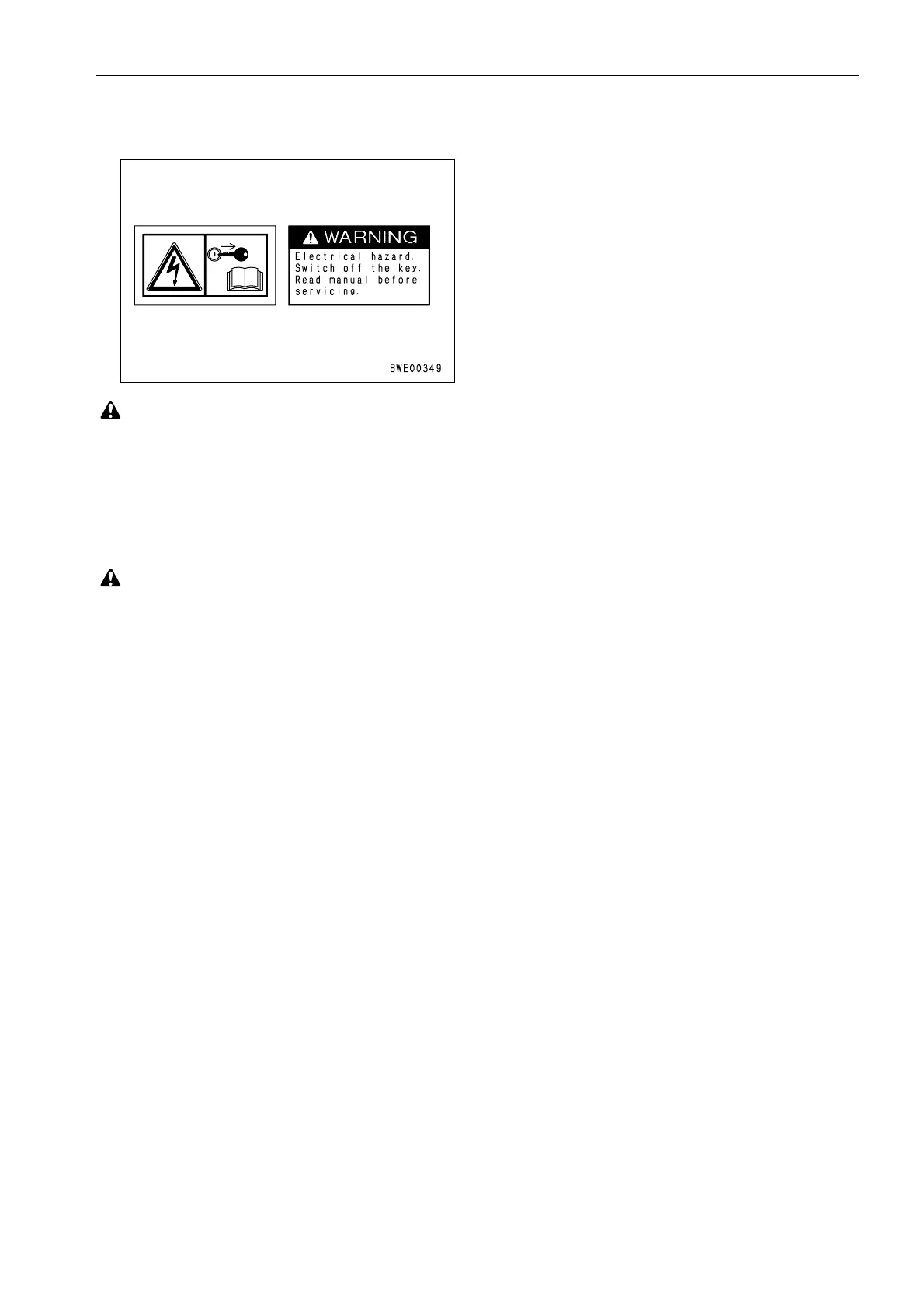
With the controller, a high voltage circuit (110 –
130V) is used for the fuel injector drive.
As a result, a high voltage circuit is connected to
the wiring harness and connector from the
controller to the fuel injector.
★ Normally, high voltage is output from the
controller to the fuel injector only when the
engine is running. When the engine is stopped,
the output stops.
If the high voltage circuit is touched directly,
there is danger of electrocution, so observe the
following precautions when carrying out
inspection.
1.
The connectors, including those for the high
voltage circuit, are as follows.
• Controller connector:
CN6
,
CN7
• Intermediate connector:
EC1
• Injector connector:
IJ1
,
IJ2
,
IJ3
,
IJ4
,
IJ5
,
IJ6
• Terminal at head of injector (inside head
cover)
2.
When disconnecting or connecting the
applicable connector, always turn the starting
switch OFF before starting.
3.
When a T-adapter has been inserted or
connected to the applicable connector to carry
out troubleshooting, never start the engine.
★ If the starting switch is operated, operate it
only to OFF or ON. Never turn it to the
START position.
 Loading...

