12-10
140-3 SERIES
TESTING AND ADJUSTING ADJUSTING VALVE CLEARANCE
ADJUSTING VALVE CLEARANCE
1.
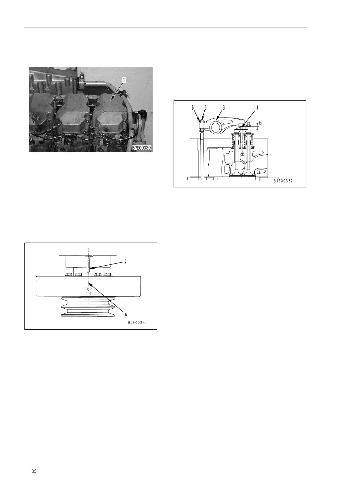
Remove cylinder head cover (1).
2.
Rotate the crankshaft in the normal direction to
set No. 1 cylinder at compression top dead cent-
er, and align pointer (2) with the [1.6] mark
a
on
the damper.
★ Crank the crankshaft with the hexagonal por-
tion at the tip of the water pump drive shaft.
★ At compression top dead center, the valve
rocker arm can be moved by hand by the
amount of the valve clearance. If the rocker
arm does not move, the crankshaft is not at
compression dead center, so rotate it one
more turn.
3.
To adjust the valve clearance, insert the feeler
gauge into clearance
b
between rocker arm (3)
and crosshead (4), and adjust the valve clear-
ance with adjustment screw (5).
★ Insert the feeler gauge and turn adjustment
screw (5) until the clearance is a sliding fit.
★ Valve clearance Intake valve: 0.35 mm
Exhaust valve: 0.57 mm
4.
Tighten locknut (6) to hold adjustment screw (5)
in position.
3
Locknut :
53.0 – 64.7 Nm {5.4 – 6.6 kgm}
★ After tightening the locknut, check the clear-
ance again.
5.
Turn the crankshaft 120º each time in the normal
direction and repeat the procedure in Steps 2 to
4 to adjust the valves of each cylinder according
to the firing order.
★ Firing order : 1–5–3–6–2–4
6.
After completing the measurement, set to the
original condition.
3
Cylinder head cover mounting bolt:
29.4 – 34.3 Nm {3.0 – 3.5 kgm}
 Loading...

