12-6
140-3 SERIES
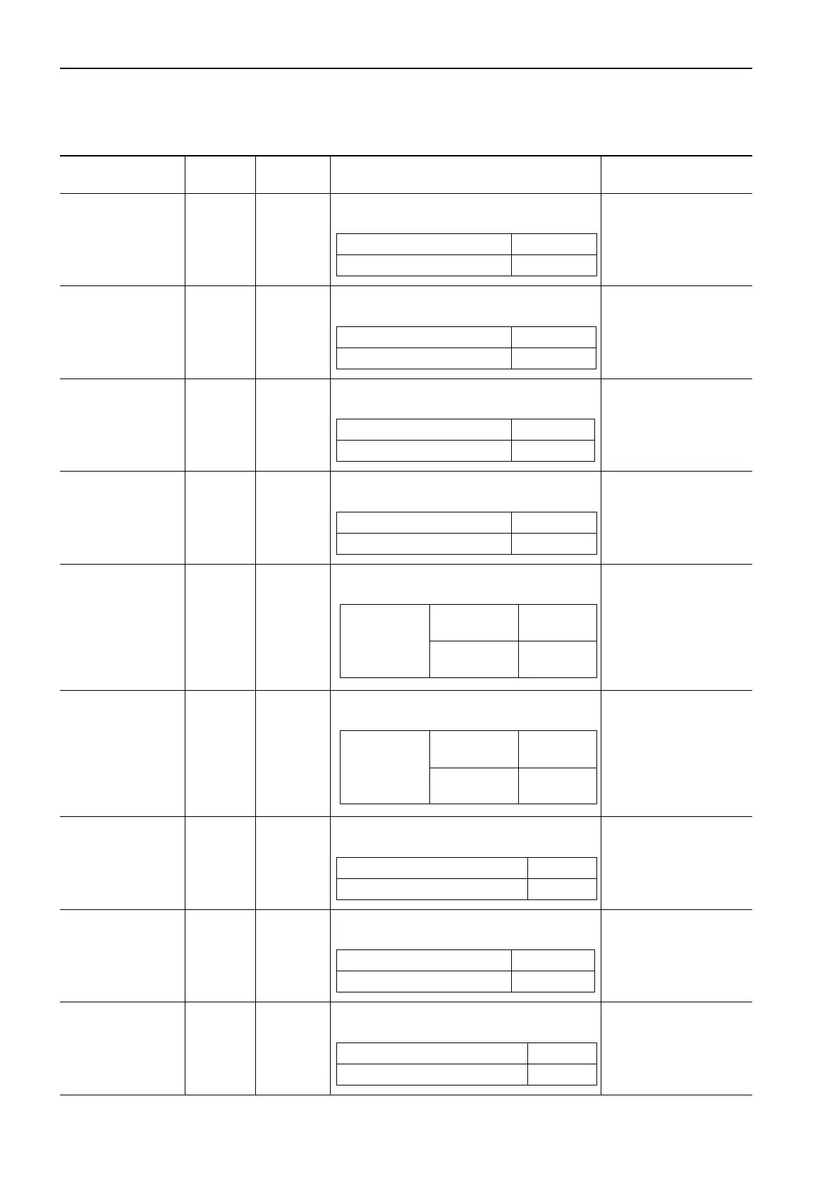
TESTING AND ADJUSTING STANDARD VALUE TABLE FOR ELECTRICAL RELATED PARTS
STANDARD VALUE TABLE FOR ELECTRICAL RELATED PARTS
Name of
component
Connector
No.
Inspection
method
Judgment table
Measurement
conditions
NE revolution
sensor
SNE
(male)
Measure
resistance
If the condition is as shown in the table
below, it is normal
1) Turn starting switch
OFF.
2) Disconnect SNE.
G revolution
sensor
SG
(male)
Measure
resistance
If the condition is as shown in the table
below, it is normal
1) Turn starting switch
OFF.
2) Disconnect SG.
Water temperature
low-temperature
sensor
TWL
(male)
Measure
resistance
If the condition is as shown in the table
below, it is normal
1) Turn starting switch
OFF.
2) Disconnect TWL.
3) Water temperature:
10 – 100ºC
Water temperature
high-temperature
sensor
TWH
(male)
Measure
resistance
If the condition is as shown in the table
below, it is normal
1) Turn starting switch
OFF.
2) Disconnect TWH.
3) Water temperature:
10 – 100ºC
Oil pressure
low-pressure
switch
POL
(male)
Measure
resistance
If the condition is as shown in the table
below, it is normal
1) Turn starting switch
OFF.
2) Disconnect POL.
Oil pressure
high-pressure
switch
POH
(male)
Measure
resistance
If the condition is as shown in the table
below, it is normal
1) Turn starting switch
OFF.
2) Disconnect POH.
Boost pressure
sensor
CN1
CN2
Measure
voltage
If the condition is as shown in the table
below, it is normal
1) Connect T-adapter
to CN1 and CN2.
2) Start engine.
Fuel temperature
sensor
TFL
(male)
Measure
resistance
If the condition is as shown in the table
below, it is normal
1) Turn starting switch
OFF.
2) Disconnect TFL
3) Fuel temperature:
10 – 100ºC
Common rail fuel
pressure sensor
CN1
CN2
Measure
voltage
If the condition is as shown in the table
below, it is normal
1) Connect T-adapter
to CN1 and CN2.
2) Start engine.
Between (1) and (2) 85 – 210
Ω
Between (1), (2) and ground Min. 1 M
Ω
Between (1) and (2) 1.4 k – 3.5 k
Ω
Between (1), (2) and ground Min. 1 M
Ω
Between (A) and (B) 9 k – 0.3 k
Ω
Between (A), (B) and ground Min. 1M
Ω
Between (1) and (2) 90 k – 3.5 k
Ω
Between (1), (2) and ground Min. 1 M
Ω
Between
terminal and
sensor
(ground)
Engine
stopped
Max. 1
Ω
600 rpm and
above
Min. 1 M
Ω
Between
terminal and
sensor
(ground)
Engine
stopped
Max. 1
Ω
1,300 rpm
and above
Min. 1 M
Ω
Between CN2 (2) and (10) 4.6 – 5.4 V
Between CN1 (3) and CN2 (10) 0.3 – 4.7 V
Between (1) and (2) 9 k – 0.3 M
Ω
Between (1), (2) and ground Min. 1 M
Ω
Between CN2 (2) and (10) 4.6 – 5.4 V
Between CN1 (3) and CN2 (10) 0.3 – 4.7 V
 Loading...

