43
Chapter 2
2.2 Component names and functions
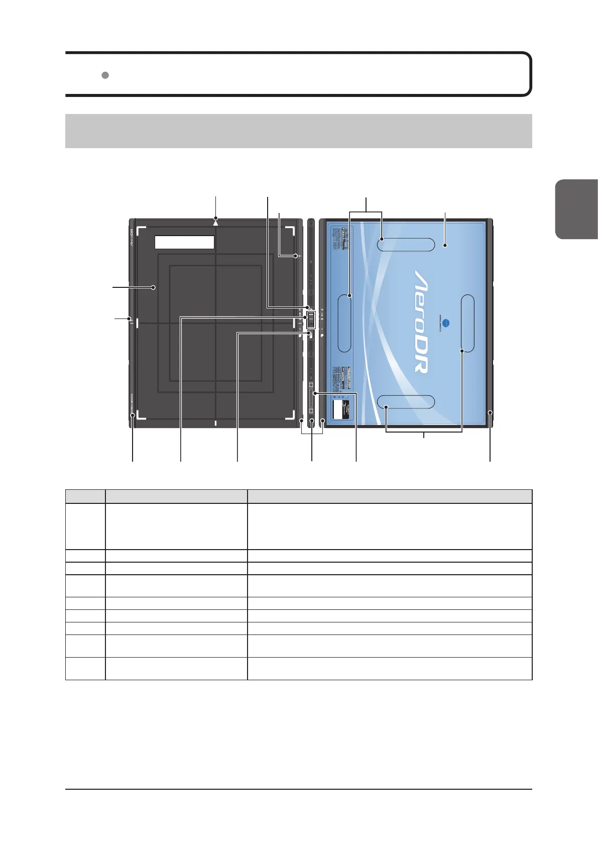
2.2.1 AeroDR 1417HQ/AeroDR 1417S/AeroDR 1717HQ/AeroDR 1012HQ
The component names and functions of the DR Detector (AeroDR 1417HQ, AeroDR 1417S,
AeroDR 1717HQ and AeroDR 1012HQ) are as follows.
(6) Protective cover
(2) Power switch
(8) Selection
switch
(9) Wired connection
connector
(5) Exterior
Exposure side
(6) Protective cover
(7) LEDs
(3) Antenna
display
(5) Exterior
(6) Protective
cover
(3) Antenna display
(1) Triangular mark (4) AeroDR Grip sheet attachment areas
(4) AeroDR Grip sheet
attachment areas
Number Name Functions
(1) Triangular mark
• Indicates the direction to place the DR Detector in during exposure.
– When exposing in portrait, place the triangular mark upward.
– When exposing in landscape, place the triangular mark to the left or right.
(Left and right are set during installation according to the exposure environment.)
(2) Power switch Used to turn the DR Detector on/o.
(3) Antenna display Displays the place where a wireless antenna is attached.
(4) AeroDR Grip sheet attachment areas
• Indicates the attachment positions for AeroDR Grip sheet use.
• The AeroDR 1012HQ does not have AeroDR Grip sheet attachment areas.
(5) Exterior Protects the internal parts.
(6) Protective cover Absorbs external shocks.
(7) LEDs Indicate the status of the DR Detector.
(8) Selection switch
Noties the image processing controller that this DR Detector will be used for
the exposure.
(9) Wired connection connector
Connects to the AeroDR Battery Charger, AeroDR Battery Charger2, wired cable,
and AeroDR UF Cable.
 Loading...