53
Chapter 2
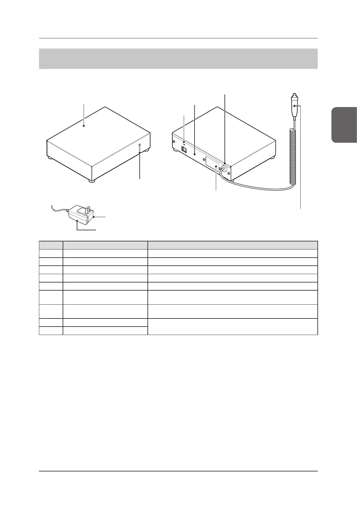
2.2 Component names and functions
2.2.11 Generator Interface Unit 3
The component names and functions of the Generator Interface Unit 3 are as follows.
(8) Power plug
(9) AC adapter
(1) Cover
(5) LED
(2) LAN port
(6) Location for connecting the
GIU3 Serial I/F Kit or GIU3 AC Adapter
(3) Base
(4) X-ray link cable outlet
(7) Hand switch
Number Name Functions
(1) Cover Protects the internal parts.
(2) LAN port Connects to the Ethernet cable.
(3) Base Protects the internal parts.
(4) X-ray link cable outlet Outlet for various X-ray link cables.
(5) LED Indicates the status of the Generator Interface Unit 3.
(6)
Location for connecting the
GIU3 Serial I/F Kit or GIU3 AC Adapter
Positions to attach GIU3 Serial I/F Kit or GIU3 AC Adapter. The illustration
shows an example with GIU3 AC Adapter attached.
(7) Hand switch
When S-SRM connection is adopted, a hand switch is installed in the Generator
Interface Unit 3.
(8) Power plug
Used to supply power to the Generator Interface Unit 3.
(9) AC adapter

 Loading...