Basics for wiring according to EMC
Requirements on the cables
6
Basic unit wiring
6.3
6.3.1
L
6.3-1
EDS82EV903-1.0-11/2002
6.3 Basics for wiring according to EMC
6.3.1 Requirements on the cables
l Only use shielded, four-core motor cable (core U, V, W, PE and overall
shield).
l Cables with a YCY copper braid have a good shielding effect, cables with
SY steel-tape armour are less suitable (high shield resistance).
l The contact ratio of the braid:
– At least 70% to 80% with overlap angle 90°
–
l Use low-capacity cables to minimise the leakage currents.
– The values depend on the cable cross-section.
l The rated voltage of the motor cable for inverter operation amounts to
Uo/U= 0.6/1 kV.
l The cables used must comply with the required approvals of the application
(e.g. UL).
The EMC safety for the temperature monitoring of the motor depends on how the
shielded connecting cables are layed.
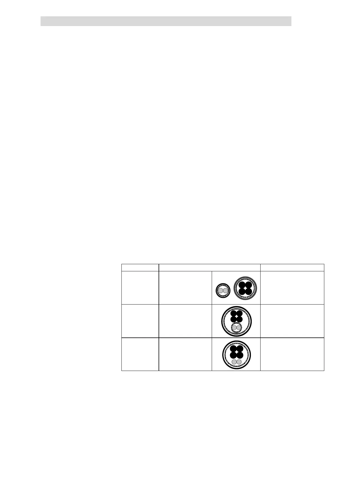
EMC safety 4 Type of laying Comment
Very good Motor cable and PTC/thermal
contact cable are layed
separately
Ideal t ype of laying with ver y low
interference injections
Use PTC/thermal contact cable as a
control cable
Medium Motor cable and PTC/t hermal
contact cable are layed
together with separate
shields
Type of laying is permitted but
show higher interference injections
Unfavorable Motor cable and PTC/thermal
contact cable are layed
together with a common
shield
High-energy interference injections
l These DC cables must be designed as the motor cable.
– Shielding
– Rated voltage
– Approval
l Being relatively short, low-capacity versions are not necessary.
Control cables must be shielded to minimise interferences.
Motor cable design
Cable design for DC supply and
brake resistor
Control cable design
 Loading...