Parameter setting with the E82ZBC keypad
Installation and commissioning
9
Parameter setting
9.3
9.3.2
L
9.3-2
EDS82EV903-1.0-11/2002
9.3.2 Installation and commissioning
)
))
) Note!
The keypad is rear-mounted to the terminal with a screw (remove
rubber protection).
The keypad can be mounted into a control cabinet door using the
”Mounting kit for control cabinets” E82ZBHT (board cutout 45.3
mm x 45.3 mm).
E82ZWLxxx
E82ZBB
E82ZBC
z
y
wx
v
t
u
s
88888
8888
888
8
abcde
j gfkih PS
mno
p
qr
Hi
Hz
%sh
rpm
°C
Ω
m
AV
Lo
z
y
wx
v
t
u
s
88800
0050
000
1
abcd e
j g fkihPS
mno
p
qr
Hi
Hz
%sh
rpm
°C
Ω
m
AV
Lo
z
y
wx
v
t
u
s
88800
0050
000
1
abcd e
j g fkihPS
mno
p
qr
Hi
Hz
%sh
rpm
°C
Ω
m
AV
Lo
8
8
8
8
8
8888
88
8
8
a
b
c
d
e
j
g
f
k
i
h
P
S
m
n
o
p
q
r
H
i
H
z
%
sh
r
p
m
°
C
Ω
m
AV
L
o
z
y
w
x
v
t
u
s
88888
8888
888
8
abcde
jgf kihPS
mno
p
qr
Hi
Hz
%sh
rpm
°C
Ω
m
AV
Lo
z
y
wx
v
t
u
s
88800
0050
000
abcde
j g fkih PS
mno
p
qr
Hi
Hz
%sh
rpm
°C
Ω
m
AV
Lo
0
1
2
3
82ZBC018
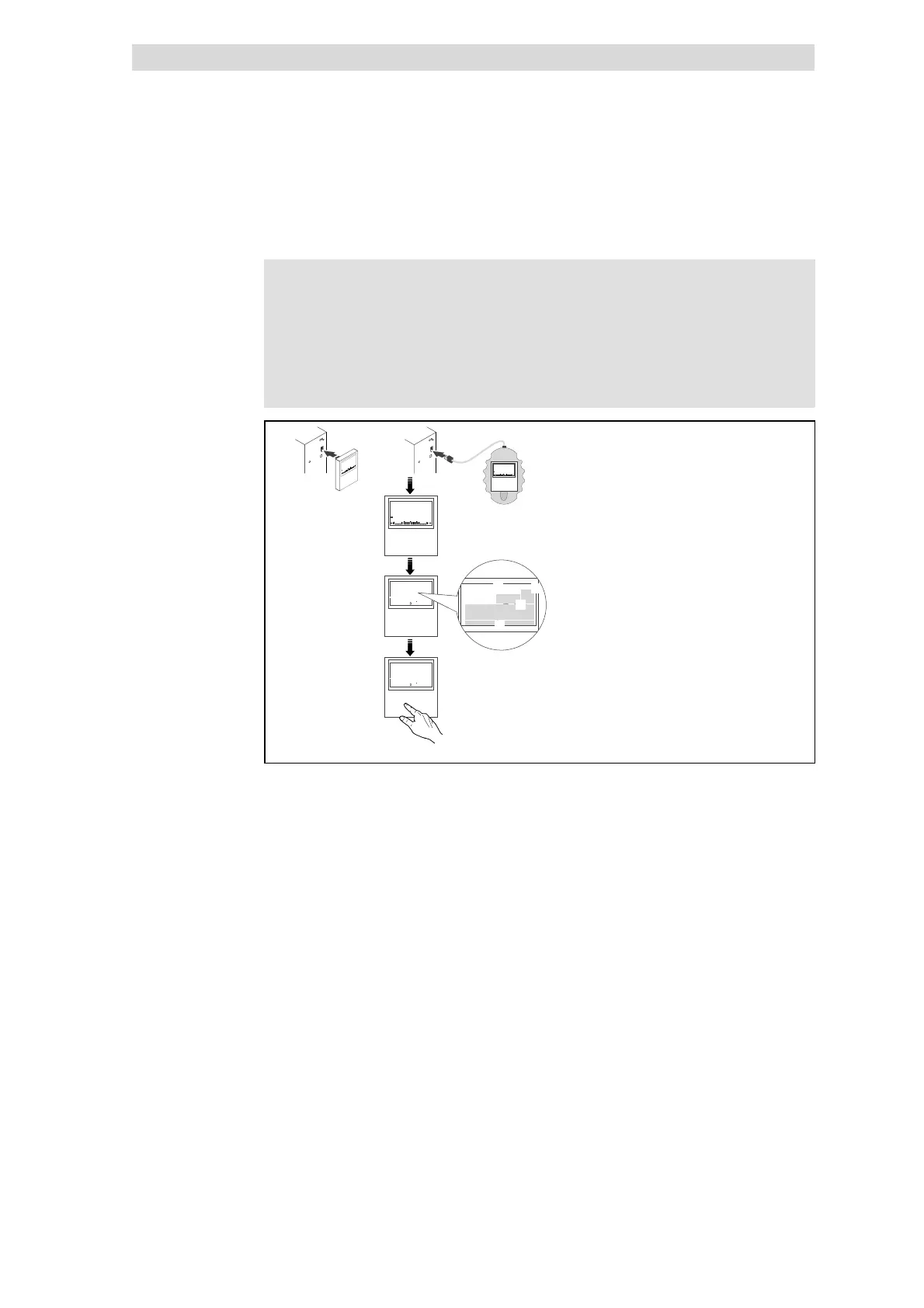
Fig. 9.3-1 Installation and commissioning of the E82ZBC keypad or E82ZBB diagnosis terminal
Connect keypad on the front of the controller to the AIF interface.
It is possible to connect the keypad and remove it during operation.
As soon as the keypad is supplied with voltage, it carries out a short self-test.
The keypad is ready for operation, if it displays the ”Disp” mode:
0 Current state of the controller
1 Parameter set activated via terminal
2 Memory location 1 of the user menu (C0517):
Code number, subcode number, and current value
3 Current value in % of the status display defined in C0004
Press
x to leave the ”Disp” mode
 Loading...