Conditions for a trouble-free network of several drives
Protection in DC-bus operation
12
Network of several drives
12.4
12.4.5
L
12.4-8
EDS82EV903-1.0-11/2002
12.4.5 Protection in DC-bus operation
You have the possibility of selecting a graded protection concept for network
operation. The damage risk depends on the type of protection. The following table
helps to analyze the risk.
)
))
) Note!
On the motor side the current limitation of the controller is an
additional cable protection. For this, the set current limitation for
the controller must correspond to the rated current of the
connected motor.
For group drives we recommend additional individual protection.
Controllers:
l The error is located between the connection at the DC bus and in the
controller before the terminals U, V, W.
Supply units:
l The error is located between the mains input (terminals L1, L2, L3) and the
farthest point of the DC bus.
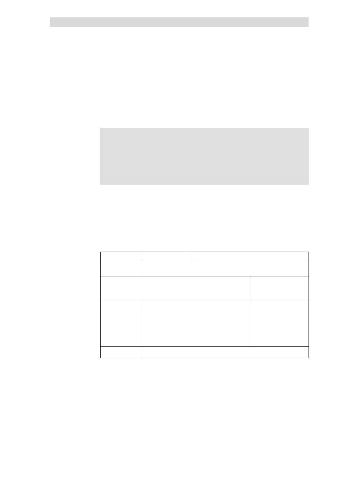
Cable protection No unit protection
Protection of • on the mains side
• on the DC-bus
• on the motor side
Possible faults One/several controllers with
• internal short circuit (+U
DC
→ -U
DC
)
• internal earth fault (+U
DC
→PE/-U
DC
→PE)
• motor-side earth fault on phase W
Mains failure of a controller
with decentralised supply .
Risk Several parallel controllers supply the error location(s) via
the DC bus. This may lead to an overload of the intact
controllers, as the faulty controller is not selectively
activated on the DC bus.
Possible damage with central and decentralised supply
• Destruction of the faulty controller
• Destruction of the controllers still intact
• Destruction of the supply unit
If a mains-side supply terminal
fail s because F1...F3 blow, the
active controllers in the
network can be overloaded.
Comment The extent of destruction depends on the ratio ”DC-bus power of the whole system / rated
power of the controller concerned”.
Protection concept and damage
risk
Definition ”Internal error”
Fuses
With mains fuses without
monitoring function (F1 ... F3)
 Loading...