Basic units in the power range of 15 ... 90 kW
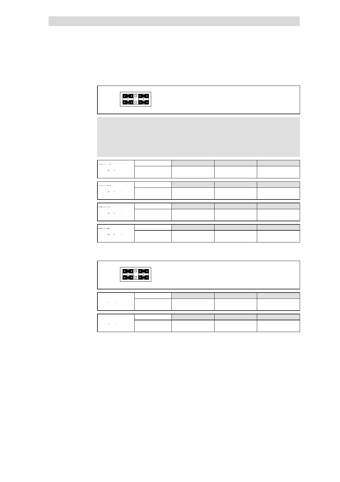
Terminal assignment - Application I/ O E82ZAFA
7
Extensions for automation
7.4
7.4.4
L
7.4-10
EDS82EV903-1.0-11/2002
10
9
8
7
2
1
4
3
j6
5
Lenze setting (see bold print in tables)
1-3
2-4
7-9
8-10
)
))
) Note!
If a setpoint potentiometer is internally supplied through X3.2/9,
the jumper must be set for a voltage range of 0 ... 5 V. Otherwise
it is not possible to provide the whole speed range.
X3.1/1U Possible levels
0 ... 5 V 0 ... 10 V
2)
-10V...+10V
Analog input1, AIN1
Jumper 7-9:free 7-9 7-9
27
Code C0034/1 = 0 C0034/1 = 0 C0034/1 = 1
X3.1/2U Possible levels
0 ... 5 V 0 ... 10 V
2)
-10V...+10V
Analog input2, AIN2
Jumper 8 - 10: free 8-10 8-10
Code C0034/2 = 0 C0034/2 = 0 C0034/2 = 1
X3.1/1I Possible levels
0 ... 20 mA 4 ... 20 mA 4 ... 20 mA
1)
Analog input1, AIN1
Jumper optional optional optional
Code C0034/1 = 2 C0034/1 = 3 C0034/1 = 4
X3.1/2I Possible levels
0 ... 20 mA 4 ... 20 mA 4 ... 20 mA
1)
Analog input2, AIN2
Jumper optional optional optional
Code C0034/2 = 2 C0034/2 = 3 C0034/2 = 4
1)
Open-circuit monitoring
2)
Lenze setting (condition when supplied)
10
9
8
7
2
1
4
3
j6
5
Lenze setting (see bold print in tables)
1-3
2-4
7-9
8-10
X3.1/62
Possible levels
0 ... 10 V 0 ... 20 mA 4 ... 20 mA
Analog output,
Jumper 1-3 3-5 3-5
AOUT1
Code C0424/1 = 0 C0424/1 = 0 C0424/1 = 1
X3.1/63
Possible levels
0 ... 10 V 0 ... 20 mA 4 ... 20 mA
Analog output,
Jumper 2-4 4-6 4-6
AOUT2
Code C0424/2 = 0 C0424/2 = 0 C0424/2 = 1
Configuration of analog inputs
and outputs
 Loading...