Speed control
15
Application examples
15.5
L
15.5-2
EDS82EV903-1.0-11/2002
)
))
) Note!
Every digital speed sensor which meets the requirements can be
used.
l The maximum frequency of inductive sensors is usually between 1 and 6
kHz, depending on its design.
l At the detection point, the number of attenuation cams per revolution must
ensure an output frequency of the sensor as high as possible.
l The control dynamics will be sufficient if the output frequency (f
act.
)is>0.5
kHz at rated speed.
l If the current consumption of the sensor is not higher than the value
permitted at X3/20, a 3-conductor sensor can be directly connected to the
controller.
Output frequency calculation
f
act=
z ⋅ n
60
z = Number of cams per revolution
n = Speed at detection point in [min
-1
]
f
act.
= Output frequency of the sensor in [Hz]
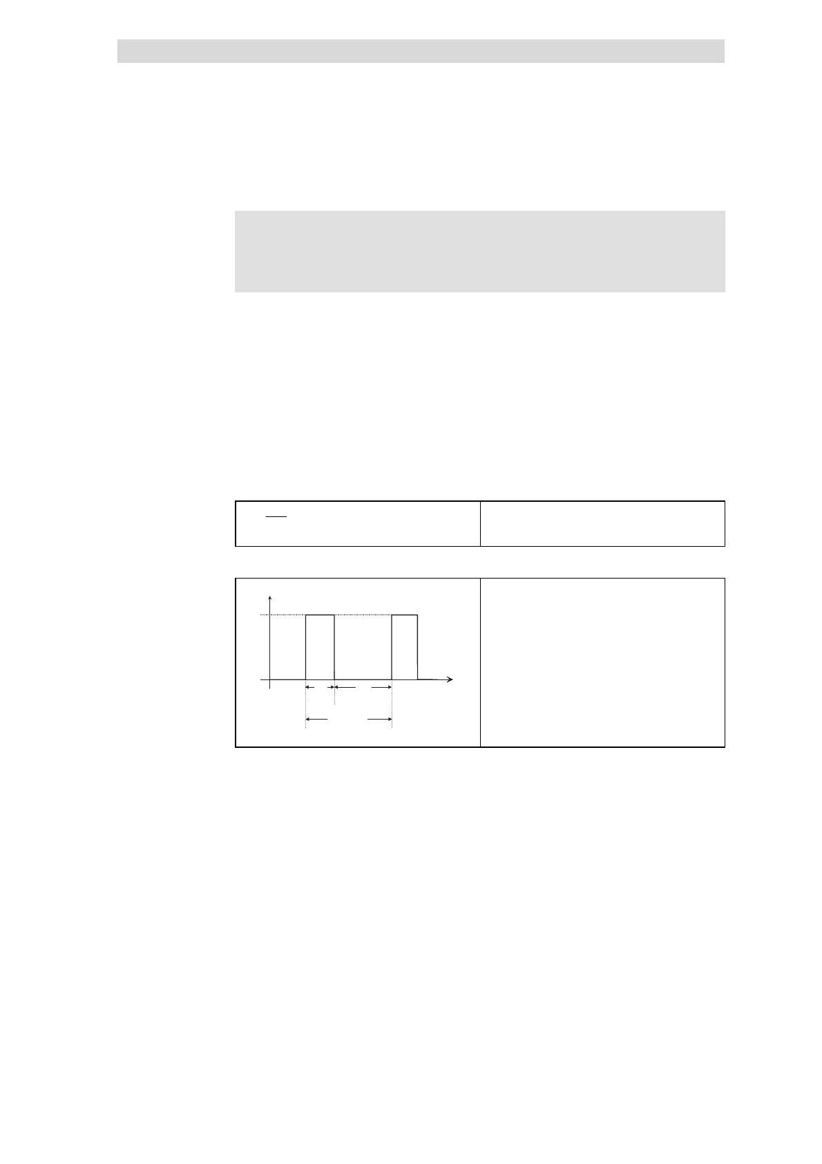
Permissible pulse shapes at X3/ E1
T
³
1 0 0
m
s
T e
T a
1 5 V
U
E 1
t
0
0
• T
e
= On (HIGH)
• T
a
=Off(LOW)
Permissible level range:
• LOW: 0 ... +3 V
• HIGH: +12 ... +30 V
Permissible range of the scanning ratio:
• T
e
:T
a
=1:1toT
e
:T
a
=1:5
Speed sensor requirements
 Loading...