Electrical installation
Wiring of the feedback system
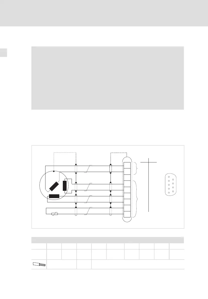
Resolver connection
5
124
EDKCSEX064 DE/EN/FR 6.0
5.5.1 Resolver connection
Note!
ƒ Use the prefabricated Lenze system cables for the connection of
a resolver.
ƒ Cable length: max. 50 m
ƒ Depending on the cable length and resolver used parameterise
the code C0416 (resolver excitation amplitude).
Check the resolver control with code C0414 (recommended
values: 0.5 ... 1.2; ideal value: 1.0).
ƒ Before using a resolver from another manufacturer, please
consult Lenze.
Connect a resolver via the 9−pole Sub−D socket X7.
Features
ƒ Resolver: U = 10 V, f = 4 kHz
ƒ Resolver and resolver supply cable are monitored for open circuit (fault
message "Sd2").
+REF
-REF
+COS
-COS
+SIN
-SIN
R1 (+KTY)
R2 (-KTY)
KTY
1
2
3
4
5
6
7
8
9
X7
0.14
26
0.5
20
mm
2
AWG
Æ
1
5
6
9
X7
ECSXA022
Fig. 5−12 Resolver connection
Assignment of socket connector X7: Sub−D 9−pole
Pin 1 2 3 4 5 6 7 8 9
Signal +Ref −Ref GND +COS −COS +SIN −SIN R1
(+KTY)
R2
(−KTY)
0.5 mm
2
(AWG 20)
˘
0.14 mm
2
(AWG 26)
 Loading...


