68
EDKCSEX064 DE/EN/FR 6.0
0Fig. 0Tab. 0
Scope of supply
Position Description Number
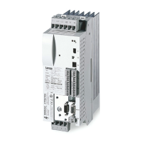
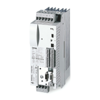
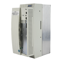
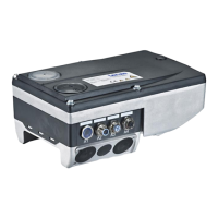
A ECSE axis module xxx 1
C Accessory kit with fixings 1
Mounting instructions 1
Drilling jig 1
Application software: S = Speed & Torque P = Posi & Shaft
M = Motion A = Application
Note!
The ECSZA000X0B connector set must be ordered separately.
Connections and interfaces
Position Description Detailed
information
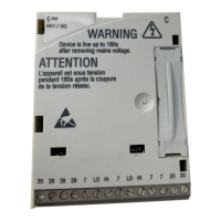
X23 Connections
l DC−bus voltage
l PE
99
B LEDs: Status and fault display
X1 Automation interface (AIF) for
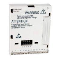
l Communication module
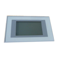
l Operating module (keypad XT)
x2 PE connection of AIF
X3 Analog input configuration 111
X4 CAN connection
l MotionBus (CAN) / for ECSxA: System bus (CAN)
l Interface to the master control
119
X14 CAN−AUXconnection
l System bus (CAN)
l PC interface/HMI for parameter setting and diagnostics
X6 Connections
l Low−voltage supply
l Digital inputs and outputs
l Analog input
l "Safe torque off" (formerly "safe standstill")
106
110
111
113
S1 DIP switch
l CAN node address
l CAN baud rate
X7 Resolver connection 124
X8 Encoder connection
l Incremental encoder (TTL encoder)
l Sin/cos encoder
125
X25 Brake control connection 104
X24 Motor connection 103
 Loading...
