Installation
821XKlimaBA0399 4-15
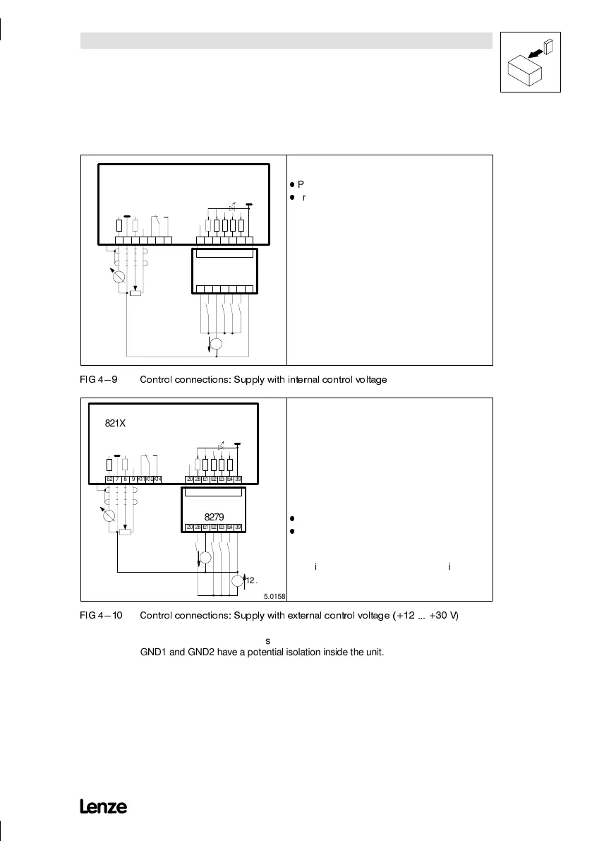
4.2.3.4 Connection diagrams of analog plug-in
modules
62 7 8 9 K11K12K14 20 28 E1 E2 E3 E4 39
821X
20 28 E1 E2 E3 E4 39
8279
GND1
GND2
VCC15
5%
GND
0 ... 10V
R
K35.0157
Connection
Voltage supply for the 8279 plug-in module:
-
Plug the module on the controller.
-
Bridge terminals 7 and 39.
Note:
With this type of wiring there are 2 or more wires
connected to one terminal. To avoid this, provide an
external connection facility.
),* &RQWURO FRQQHFWLRQV 6XSSO\ ZLWK LQWHUQDO FRQWURO YROWDJH
K35.0158
62 7 8 9 K11K12K14 20 28 E1 E2 E3 E4 39
821X
20 28 E1 E2 E3 E4 39
8279
12 ... 30V
GND1
GND2
VCC15
5%
GND
0 ... 10V
R
Danger!
There is no mains isolation between external supply and
unit mass.
There is no double mains isolation between the mains
and the terminals.
Therefore, the unit is not electrically isolated, i.e. not
protected against contact.
Connection
Voltage supply for the 8279 plug-in module:
-
Plug the module on the controller.
-
Bridge terminals 7 and 39.
Note
With this type of wiring there are 2 or more wires
connected to one terminal.To avoid this, provide an
external connection facility.
),* &RQWURO FRQQHFWLRQV 6XSSO\ ZLWK H[WHUQDO FRQWURO YROWDJH 9
GND1 Reference for internal voltages
GND2 Reference for external voltages
GND1 and GND2 have a potential isolation inside the unit.
 Loading...