EMC-compliant installaon
The drive system (inverter and drive) only complies with the EMC Direcve 2014/30/EU if it is installed
according to the guidelines for CE-typical drive systems.
These guidelines should also be followed in installaons requiring FCC Part 15 or ICES 001 compliance.
NOTICE
Electromagnec interference
Product and peripheral devices may be aected during operaon.
▶
Please use suciently conducve shield connecons.
▶
Connect the housing with shielding eect to the grounded mounng plate with a surface as large as
possible, e. g., inverters and RFI lters.
▶
Use central earthing points.
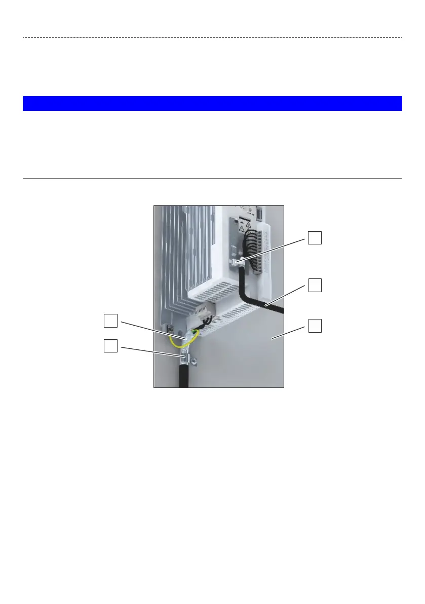
The example below shows the eecve wiring:
A Shield connecon for control cables
B Control cable
C Mounng plate with conducve surface
D Shield connecon for motor cable
(alternavely: shield connecon on an
oponal motor shield plate)
E Motor cable with low capacity
EMC-compliant installaon must be implemented with shielded motor cables with low capacitance.
Capacitance per unit length:
•
C-core-core/C-core-shielding: < 75/150 pF/m ≤ 2.5 mm² (≥ AWG 14)
•
C-core-core/C-core-shielding: < 150/300 pF/m ≥ 4 mm² (≤ AWG 12)
Electrical installaon
EMC-compliant installaon
30
 Loading...


