3-phase mains connecon 230/240 V
Connecon diagrams
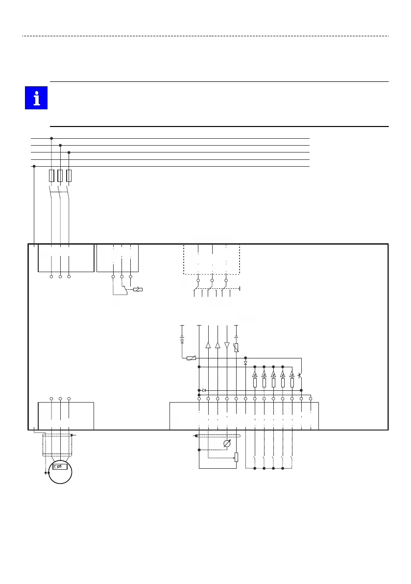
The connecon plan is valid for the inverters I51AExxxC.
Inverters I51AExxxC do not have an integrated RFI lter in the AC mains supply.
In order to meet the EMC requirements according to EN 61800−3, an external EMC lter according
to IEC EN 60939 must be used.
The user must verify that the conformity with EN 61800−3 is fullled.
/ CL TA
/ CG COM
/ CH TB
X216
CANopen/Modbus
Modbus
CH
TB
CL
TA
CG
COM
1k ... 10k
0 ... 10 V
S1
"
100 mA
+24 V
Basic I/O
GND
1 DO
4.4k
1 DI
4.4k
2 DI
4.4k
3 DI
4.4k
4 DI
4.4k
5 DI
1 AI
2 AI
+10 V
10 mA
10V
GND
1 AO
24V
X3
X105
U
V
W
+
"
M
3~
+
J
J
NC
NO
COM
X9
AC 240 V
3 A
X100
L1
L2
L3
F1
…
F3
Q1
3/N/ PE
208 V ... 240 VAC
3/ PE
170 V ... 264 VAC
45 Hz ... 65 Hz
PE
N
L3
L2
L1
+
Fig. 3: Wiring example
S1 Start/Stop
Fx Fuses
Q1 Mains contactor
--- Dashed line = opons
Electrical installaon
Mains connecon
3-phase mains connecon 230/240 V
38
 Loading...


