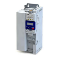
Inial switch-on and funconal test
Target: Get the motor connected to the inverter to rotate in best me.
Necessary condions:
•
The power rang of the motor connected is appropriate for the inverter.
•
The parameter sengs correspond to the delivery status (Lenze seng).
1. Preparaon
1.
Wire the power connecons. 4Electrical installaon ^ 29
2. Wire digital inputs X3/DI1 (start/stop), X3/DI3 (reversal) and X3/DI4 (frequency preset 20 Hz).
3. Do not wire terminal X3/AI1 (analog setpoint selecon) or set to GND.
2. Switch on mains and check readiness for operaon
1. Switch on mains voltage.
2. Observe LED status displays "RDY" and "ERR" on the front of the inverter:
a) When the blue LED "RDY" blinks and the red LED "ERR" is o, the inverter is ready for operaon. The
controller is inhibited.
You can start the drive.
b) If the red LED "ERR" remains lit, a fault is acve.
Eliminate the fault before you carry on with the funconal test.
Carry out funconal test
1. Start drive
1. Start inverter: X3/DI1 = HIGH.
2. Acvate frequency preset 1 (20 Hz) as speed setpoint: X3/DI4 = HIGH.
The drive rotates with 20 Hz.
3. Oponal: Acvate reversal
a) X3/DI3 = HIGH.
The drive rotates at 20 Hz in the opposite direcon.
b) Deacvate reversal again: X3/DI3 = LOW.
Speed characterisc (example)
2. Stop drive
1. Deacvate frequency preset 1 again: X3/DI4 = LOW.
2. Stop inverter again: X3/DI1 = LOW.
The funconal test has been completed.
Control with Keypad
The "Keypad Full Control" control mode can be acvated with the keypad key “CTRL”. Both the control and
the setpoint selecon are then made via the keypad. This special control mode can be, for instance, used
during the commissioning phase if external control and setpoint sources are not ready to use yet.
If the local keypad control is acve, "LOC" is displayed in the lower status row of the keypad and the red LED
ashed.
•
Aer the "CTRL" key has been pressed, the acvaon of the control mode must be conrmed with the
key. (The key serves to cancel the acon.)
•
When the control mode is changed over, the motor is rst stopped and the "Forward" direcon of
rotaon is set. Then, the motor can be started and stopped via the keypad.
Commissioning
Inial switch-on and funconal test
53

 Loading...


