Project SERVICE MANUAL
Date
05-2017
3/84
Contents
1 Introduction – General information ................................................................................ 5
1.1 Product label and technical label – location ........................................................................................ 5
1.1.1 Product label description ............................................................................................................... 5
1.1.2 Technical label description ............................................................................................................ 6
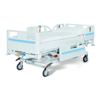
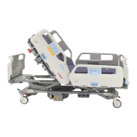
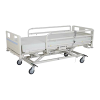
1.2 Identification of bed parts .................................................................................................................... 7
1.3 List of tools and equipment needed for servicing the bed .................................................................. 8
2 Technical data .................................................................................................................. 9
2.1 Conditions of use ................................................................................................................................ 9
2.2 Mechanical data .................................................................................................................................. 9
2.3 Electrical data ....................................................................................................................................10
3 Components ................................................................................................................... 11
3.1 Location and description of parts located on bed .............................................................................11
3.1.1 Electronic components ................................................................................................................11
3.1.2 Mechanical parts ..........................................................................................................................18
3.2 Column unit torque values ................................................................................................................19
4 Electrical devices – component connection ................................................................ 20
4.1 Bed wiring diagram ...........................................................................................................................20
4.2 Head siderail .....................................................................................................................................21
4.3 Multiboard .........................................................................................................................................22
4.4 Foot siderail .......................................................................................................................................23
4.5 Nurse Call .........................................................................................................................................24
4.6 Scale module and Nurse Call ...........................................................................................................25
4.7 Scale tensometers ............................................................................................................................26
4.8 Undercarriage module.......................................................................................................................27
4.9 Undercarriage module (version with 5th castor) ...............................................................................28
4.10 5th castor .....................................................................................................................................29
4.11 I-brake ..........................................................................................................................................30
4.12 I-Drive Power wheel.....................................................................................................................31
4.12.1 Power supply ...............................................................................................................................32
4.12.2 Drive wheel assembly ..................................................................................................................33
4.12.3 Fault signalisation ........................................................................................................................34
4.12.4 I-Drive Power - connection scheme .............................................................................................35
4.13 Night light .....................................................................................................................................36
4.14 Equipotential bonding connections ..............................................................................................37
5 Bed setup ....................................................................................................................... 38
5.1 Faulty Multiboard ...............................................................................................................................38
5.2 Positioning with a single column .......................................................................................................38
5.3 Column and accelerometer calibration .............................................................................................39
5.3.1 Column and accelerometer calibration using the LCD Multiboard panel ....................................39
5.3.2 Column and accelerometer calibration using the ACP ................................................................44
5.4 Transport lock ...................................................................................................................................46
5.5 RC circuit ...........................................................................................................................................47
5.5.1 Function description and purpose ...............................................................................................47
5.5.2 Activation / deactivating short circuit detection on the LCD panel ..............................................47
5.5.3 Activating / deactivating short-circuit detection on the ACP ........................................................50
5.6 Calibration of multizone bed exit alarm .............................................................................................51
5.7 Calibrating the i-Drive Power
®
accelerometers .................................................................................55
 Loading...