MXD73
Quick Start Guide
23 mm
134 mm
25 mm Min
For Cables
And Connectors
Screw Clamp x 4
Gasket Seal
F1
F2
F3
F4
F5
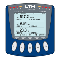
09:56
MON 1 JUN 2009
CH1:
517.2
µS/cm
i)
ii)
12.3
°C
A: 12.28mA
CH2:
9.64 pH
i)
ii)
25.0
°C
-156mV
CH3:
23.3 %
i)
ii)
28.0
°C
2.15Atm
MENU
CAL
116 mm
128 mm
TANK 1
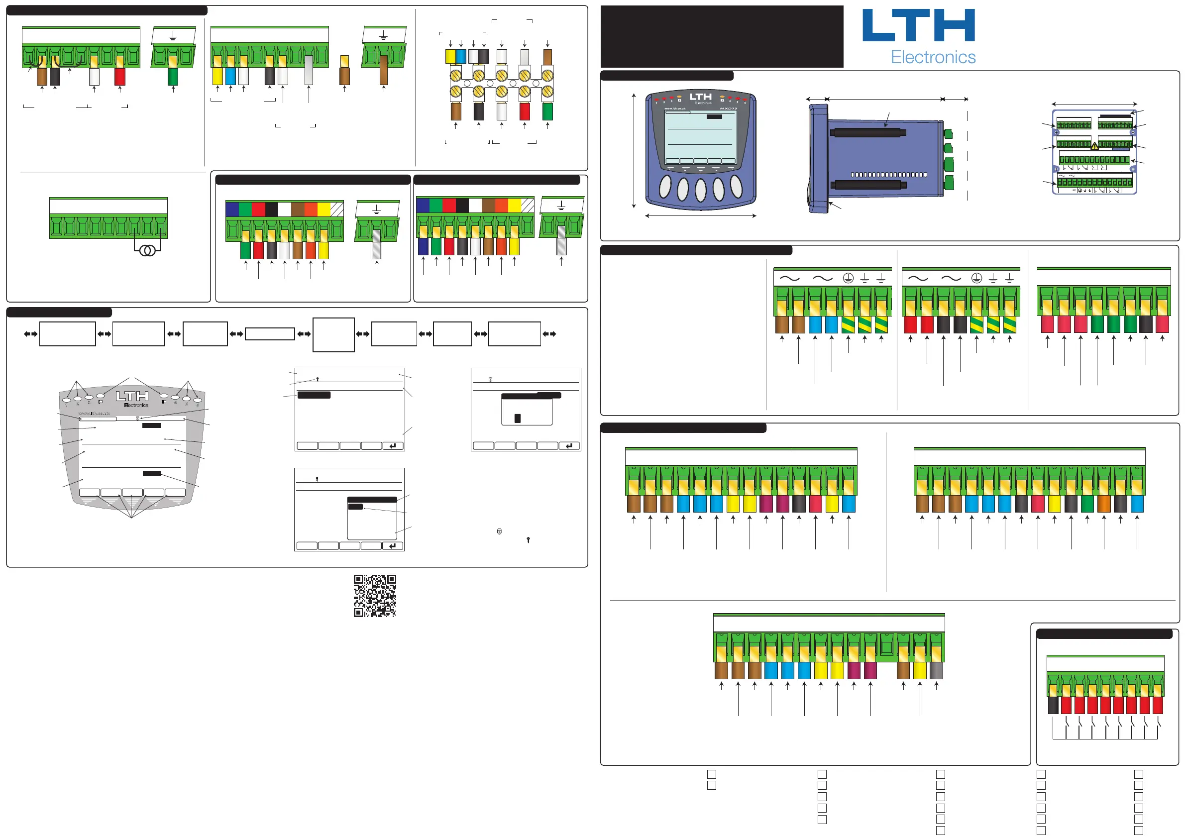
Output Option Card Connection Details
NO3 C3 NC3 NO4 C4 NC4 C6 NO6C5 NO5
Output Option Connector
A B C
Relay 3
Normally
Open
Contact
Relay 3
Common
Contact
Relay 3
Normally
Closed
Contact
Relay 4
Normally
Open
Contact
Relay 4
Common
Contact
Relay 4
Normally
Closed
Contact
Relay 5
Normally
Open
Contact
Relay 5
Common
Contact
Relay 6
Normally
Open
Contact
Relay 6
Common
Contact
Modbus A
Connection
(Inverting)
(Rx-/Tx-)
Modbus C
Connection
(0V Reference)
Optional
Modbus B
Connection
(Non-Inverting)
(Rx+/Tx+)
Modbus and 4 Relays Output Option Card Connection Details
NO3 C3 NC3 NO4 C4 NC4
Output Option Connector
E F
Relay 3
Normally
Open
Contact
Relay 3
Common
Contact
Relay 3
Normally
Closed
Contact
Relay 4
Normally
Open
Contact
Relay 4
Common
Contact
Relay 4
Normally
Closed
Contact
Current
Output B “+”
Current
Output “-”
(Common)
Current
Output “-”
(Common)
Current
Output C “+”
Current
Output E “+”
Current
Output F “+”
Current
Output “-”
(Common)
Current
Output D “+”
5 Current Outputs 2 Relays Output Option Card Connection Details
I-
-
-
I-
-
-
I-
-
-
B C D
NO3 C3 NC3 NO4 C4 NC4 C6 NO6C5 NO5
Output Option Connector
B C D
Relay 3
Normally
Open
Contact
Relay 3
Common
Contact
Relay 3
Normally
Closed
Contact
Relay 4
Normally
Open
Contact
Relay 4
Common
Contact
Relay 4
Normally
Closed
Contact
Relay 5
Normally
Open
Contact
Relay 5
Common
Contact
Relay 6
Normally
Open
Contact
Relay 6
Common
Contact
Current
Output B “+”
Current
Output D “+”
Current
Output C “+”
Current
Output “-”
(Common)
Output Option Card Connection Details.
Available Relays and Current Outputs Vary Depending On Card Type
I-
-
-
Digital Input Connection Details
Digital Input Connector
G 1 2 3 4 5 6 7 8
Digital Input Connection Details
SD CARD
DIGITAL INPUTS
OUTPUT OPTION
CH3
CH2
CH1
C
C
C
H
H
H
1
2
3
A
B
C
CONDUCTIVITY
G 1 2 3 4 5 6 7 8
PH / REDOX
ECS CONDUCTIVITY
A A B B G E C
-
E E R R
+
+ -
A A B B
A A B B -R R D D+ + -
I- B+ C+ D+
0/4 - 20mA
-
-
I- B+ C+ D+
-
-
NO3 C3 NC3 NO4 C4 NC4 C6 NO6C5 NO5
85-250V
A
-
+
L
+
N
-
1 2
0/4-20
mA
I-E E E A+
-
-
NO1 C1 NC1 NO2 C2 NC2
Power &
Standard Outputs
Connector
Output
Option
Channel 2
Channel 3
Channel 1
Digital
Inputs
SD Card
Slot
89 mm Sq
Recomended Panel Cut-Out
Should be 92mm X 92mm
Exact Instrument Conguration Depends
Upon Ordered Specication
MXD73 Instrument Dimensions
The MXD73 Panel Mount Instrument is designed to be ushed mounted and sealed in a
square cut-out in a panel, and is held in place with the four screw clamps provided
Chaul End Lane
Luton
Bedfordshire
LU4 8EZ
England
Power & Standard Outputs Connection Details
CAUTION!
Always remove the main power from the system
before any alterations to the wiring. Ensure that
both power lines are isolated. Make sure that the
power cannot be switched on by accident whilst the
instrument is being connected. For safety reasons
an earth connection must be made to the earth
terminal of this instrument.
Local wiring and safety regulations should be strictly
adhered to when installing this instrument. If the
installation methods and cable types recommended
in this guide are followed, then the instrument will
achieve the levels of EMC protection as specied in
the appropriate manual.
Consult the serial label on the side of the
instrument for supply voltage requirements.
Fitted Options- Power Supply: 24V Output Option Card: 1-Current 2-Relays Channel1: Cond Channel2: Cond Channel3: Cond
Mains 3-Current 0-Relays pH/Redox pH/Redox pH/Redox
3-Current 4-Relays ECS ECS ECS
5-Current 2-Relays DO DO DO
Modbus 4-Relays Aux mA IP Aux mA IP Aux mA IP
SS SS SS
Telephone: +44 (0)1582 593693
Fax +44 (0)1582 598036
email: sales@lth.co.uk
Web: www.lth.co.uk
Power + Basic Outputs Connector
Relay 1
Normally Open
Contact
Relay 1
Common
Contact
Relay 1
Normally Closed
Contact
Relay 2
Normally Open
Contact
Relay 2
Common
Contact
Relay 2
Normally
Closed
Contact
NO1 C1 NC1 NO2 C2 NC2
Current
Output “-”
(Common)
Current
Output A ”+”
I- A+
-
-
Standard Outputs Connection Details
Power Supply
“Live” In
Power Supply
“Live” Out
(For Daisy Chaining)
Power Supply
“Neutral In
Power Supply
“Neutral” Out
(For Daisy Chaining)
Protective Earth
(Must Be
Connected)
Earth
Earth
Power + Basic Outputs Connector
85V-265V AC/DC Power Supply
Connection Details
Power
Supply
“+” In
Power Supply
“+”Out
(For Daisy Chaining)
Power Supply
“-” In
Power Supply
“-” Out
(For Daisy Chaining)
Protective Earth
(Must Be
Connected)
Earth
Earth
Power + Basic Outputs Connector
18V-32V AC/DC Power Supply
Connection Details
MON 1 JUN 2009
09:56
CH1: 517.2 µS/cm TEMP1: 12.3°C
CH2: 9.64 pH
CH3: 23.3%
TEMP2: 25.0°C
TEMP3: 28.0°C
MAIN MENU
DIGITAL INPUTS
CHANNELS
EXIT
4-20mA OUTPUTS
CALIBRATION
SETPOINT / RELAYS
CONFIGURATION
CURSOR
FURTHER MENU
PAGES BELOW
INSTRUMENT
READINGS
CURRENT
DATE / TIME
UNIT STATUS
FURTHER MENU
PAGES ABOVE
MON 1 JUN 2009
09:56
CH1: 517.2 µS/cm TEMP1: 12.3°C
CH2: 9.64 pH
CH3: 23.3%
TEMP2: 25.0°C
TEMP3: 28.0°C
SETPOINT 1 SETUP
INPUT SOURCE:
RANGE:
TRIGGER:
HIGH VALUE:
MODE:
CHANNEL:
SENSOR
0 to 9.999 mS/cm
HIGH
7.500mS/cm
ON/OFF
EXIT
CHANNEL 1 (COND)
LOW
BAND
LATCH HIGH
TRIGGER
HIGH
LATCH LOW
CURSOR
ADDITIONAL
OPTIONS BELOW
OPTION POP-UP
MON 1 JUN 2009
09:56
CH1: 517.2 µS/cm TEMP1: 12.3°C
CH2: 9.64 pH
CH3: 23.3%
TEMP2: 25.0°C
TEMP3: 28.0°C
CHANNEL 1 SETUP
UNITS:
CELL CONSTANT:
RANGE:
TEMP INPUT SENSOR:
TEMPERATURE UNITS:
MODE:
SIEMENS(S/cm)
1.000
AUTO
PT1000
°C
EXIT
ON-LINE
SECURITY CODE
CODE
ENTER ACCESS
* * *
0
09:56
MON 1 JUN 2009
CH1:
517.2 µS/cm
i)
ii)
12.3°C A:12.28mA
CH2:
9.64 pH
i)
ii)
25.0°C -156mV
CH3:
23.3 %
i)
ii)
28.0°C 50.15 µS/cm
MENUACK
DOSE ALARM
CAL
CURRENT DATE
UNIT STATUS
CURRENT TIME
CHANNEL
MESSAGES
CHANNEL SECONDARY
READING ii
CONTEXT SENSITIVE BUTTON FUNCTIONS
CHANNEL PRIMARY
READING
CHANNEL ID
CHANNEL SECONDARY
READING i
CHANNEL ALARM
STATUS
SETPOINT STATUS
LEDS
SETPOINT STATUS
LEDS
ALARM STATUS
LEDS
TANK 1
TANK 3
CHANNEL
LABEL
User Interface Overview
Scrolling Menu Layout
Front Layout
Main Menu Layout
Pop-Up Option Layout
Security Access Pop-Up
To protect the instrument setup
from unauthorised or accidental
tampering, a security access code
system is present. This is
implemented via the instrument’s
menu system which operates in two
modes, “locked” as indicated by a
padlock symbol and “unlocked” as
indicated by a key symbol.
Part No. 6128
Seventh Issue February 2019
Copyright LTH Electronics Ltd.
The default Access Code is: 1000
Front Screen
Current
Output
Bargraphs
Channels
Setup
Setpoint /
Relays Setup
4-20mA
Outputs Setup
Digital
Inputs Setup
Error
Messages
Live Trends
1, 2 & 3*
*Optional Extra
For conguration and calibration information please consult
the operational manuals available online at -
lth.co.uk/index.php/downloads/ or via the adjacent QR code.
A
Brown
B
Black
Anode
Red
Broadley James ProcessProbe™ Polargraphic
Dissolved Oxygen Sensor Cable
Connection Details
Unit Earth TerminalDissolved Oxygen Input Connector
Cathode
White
Link
Link
GPA A B B T C AAP
Green
(Outer Screen)
Sensor Input
Temperature Input
Standard Dissolved Oxygen Input Card Connection Details
Unit Earth Terminal
Dissolved Oxygen Input Connector
GPA A B B T C AAP
Anode
(White Core
Screen)
BrownWhite
Yellow
54D Extension Cable Connection Details
Cable Outer
Screen
Cathode
(White
Core)
Not
Connected
Sensor Input
Temperature Input
Blue
Black
Anode
(White Core
Screen)
54D Extension Cable
Sensor Input
Yellow Blue White Black
Temperature Input Cable Outer
Screen
Cathode
(White
Core)
“TC”
(Black)
“CATH”
(White)
“ANOD”
(Red)
“TC”
(Brown)
Green
Temperature Input Sensor Input
Broadley James ProcessProbe™ Sensor Cable
Broadley James ProcessProbe™ Cable To
54D Extension CableConnection Details
Pressure Transmitter
Connection Details
Dissolved Oxygen Input Connector
GPA A B B T C AAP
-+
4-20mA
Suspended Solids Input Card Connection Details
Suspended Solids Input Connector
Cable Screen
Unit Earth Terminal
Green
Red
Black
White
Brown
Orange
Yellow
Turbidity Input Connector
Cable Screen
Unit Earth Terminal
Green
Red
Black
White
Brown
Orange
Yellow
Blue
T30 Turbidity Sensor Cable
Connection Details
Turbidity Input Card Connection Details
 Loading...