Grove Published 3-25-2020, Control # 643-04 4-19
GRT880 OPERATOR MANUAL SET-UP AND INSTALLATION
ERECTING AND STOWING BI-FOLD BOOM
EXTENSION WITH 6 M (20 FT) INSERT
Erecting
NOTE: Auxiliary boom nose (rooster sheave) does not
have to be removed. However, if reeved, the hoist
cable must be removed from the sheave.
1. Fully extend and set outriggers.
2. Position boom over front of crane.
3. Fully retract the boom.
4. Lower boom to minimum elevation.
5. If not already done so, deploy the boom extension by
performing the procedures under Erecting Boom
Extension, page 4-11, but do not make the anti-two
block connection or hydraulic connection (if required) at
the boom nose.
6. Extend boom as necessary to permit sufficient
clearance for installation of the 6.1 m (20 ft) Extension
Insert, then lower it until tip of boom extension is laying
on the ground. Block under boom extension,
approximately 2.4 m to 3.0 m (8 ft to 10 ft) ahead of the
boom nose.
7. Remove four retainer clips and attachment pins that
secure boom extension to the boom nose.
8. Retract boom leaving boom extension on blocking.
9. Using main or auxiliary hoist cable, lift Insert by the lifting
lugs and position it at base end of boom extension.
10. Attach Insert to boom extension by installing the four
attachment pins and retainer clips removed in step 7.
11. With hoist cable still attached to Insert, lift assembled
unit. Move blocking erected in step 6, 2.4 m to 3.0 m (8 ft
to 10 ft) ahead of boom nose attachment end of Insert.
12. Lower boom extension and insert assembly to blocks.
Remove hoist cable.
13. Retract boom and lower to minimum elevation.
14. Rig hoist cable for single part line with only wedge
socket on cable end.
15. Extend boom and mate anchor fittings on Insert with
attachment fittings on boom nose. Raise or lower boom
slightly to mate attachment anchor fittings as needed.
NOTE: If Insert anchor fitting holes are not in lateral
alignment with holes in the boom nose attachment
fittings to install the pins, adjust upper and lower
cross strut adjustment screws on the Insert to align
the holes.
16. Remove retainer clips from attachment pins stowed on
Insert. Install in attachment and anchor fittings on both
sides of boom nose. Install retainer clips.
17. Make anti-two block electrical connections between the
insert and the boom nose and boom extension.
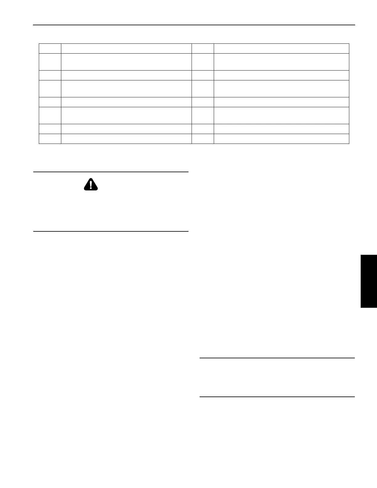
Item Description Item Description
1
Boom Extension Fly Section Rear Stowage
Bracket Assembly
8 Offset Link
2 Boom Extension Fly Section 9 Boom Extension Locking Bar
3
Boom Extension Fly Section Front Stowage
Ramp Assembly
10 Middle Stowage Bracket and Actuator Assembly
4 Boom Extension Fly Section Sheave 11 Boom Extension Base Section
5
Boom Extension Base Section Front Stowage
Bracket Assembly
12 Boom Extension Base Section Sheave
6 Boom Extension Mast Assembly 13 Lock Hitch Pin
7 Offset Link Pinning Locations 14 Front Stowage Bracket Pins
DANGER
Crushing Hazard!
Before attempting to erect or stow bi-fold extension with
insert, read and follow all safety decals installed on
boom/boom nose, boom extension, insert, and stowage
brackets.
CAUTION
Possible Equipment Damage!
Do not attempt to swing boom extension to right side of
insert. Damage to insert may result.

 Loading...


