OPERATING CONTROLS AND PROCEDURES GRT880 OPERATOR MANUAL
3-14 Published 3-25-2020, Control # 643-04
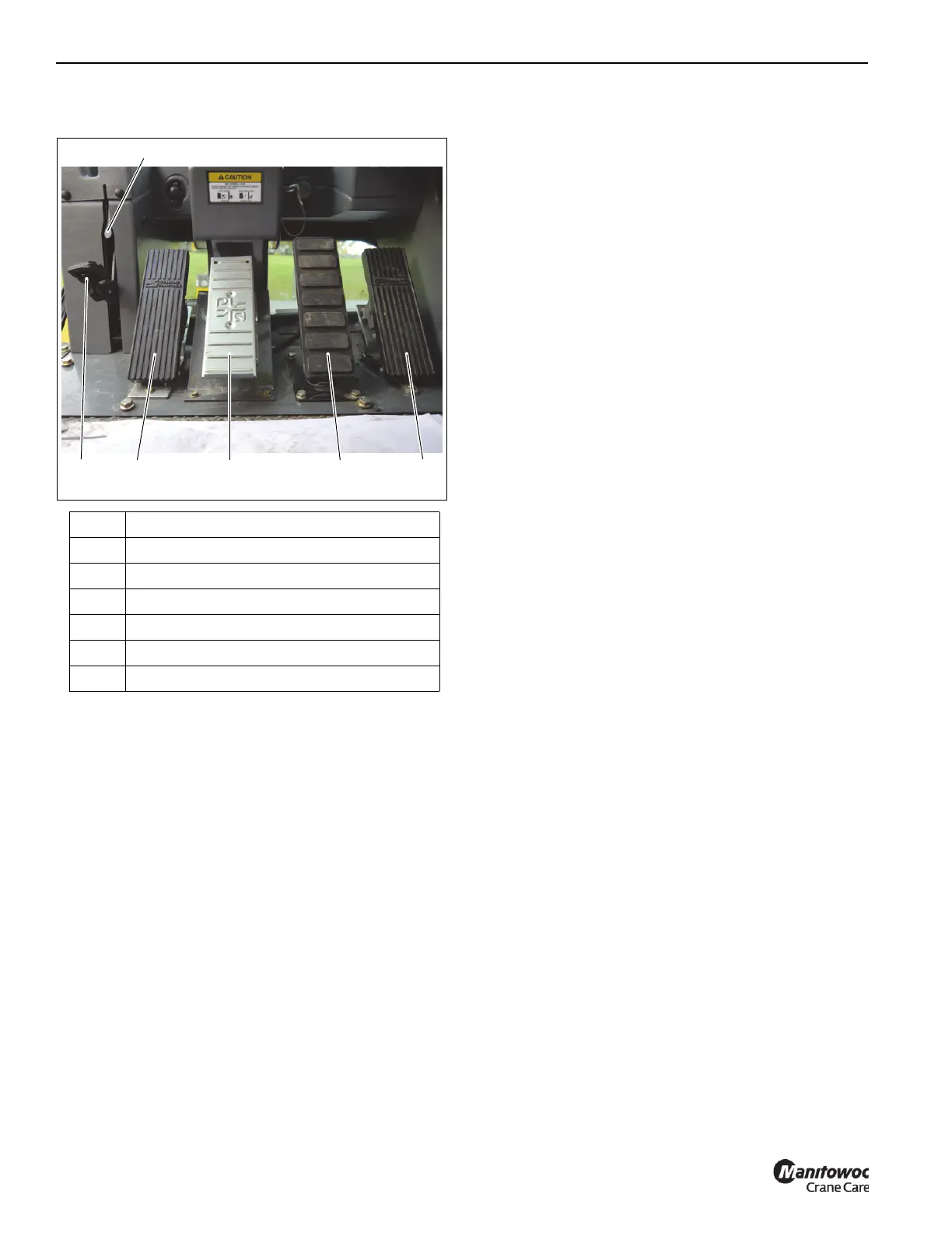
FOOT PEDAL CONTROLS
360° Swing Lock Pedal
The 360° Swing Lock Pedal (1) (Figure 3-8) is located on the
left side of the cab floor. The pedal activates the swing lock to
prevent superstructure from turning. To release the swing
lock, pull up the 360° Swing Lock Release Lever (2).
Swing Brake Pedal
The Swing Brake Pedal (3) (Figure 3-8) is located on the left
side of the cab floor. It actuates the swing brake to slow or
stop swing motion. Braking increases or decreases
proportionately with the amount of foot pressure applied to
the pedal.
Telescope Control Pedal (Optional)
The Telescope Control Pedal (4) (Figure 3-8) is located in
the middle of the cab floor. Pushing top of pedal extends the
boom. Pushing bottom of pedal retracts the boom.
Service Brake Pedal
The Service Brake Pedal (5) (Figure 3-8) is the second pedal
from the right on the cab floor. Pressing the pedal controls
application of the service brakes.
Foot Throttle Pedal
The Foot Throttle Pedal (6) (Figure 3-8) is located on the
right side of the floor. It controls engine RPM which increases
or decreases proportionately with the amount of foot
pressure applied to the pedal. The pedal is electrically
connected to the superstructure control module which sends
the signal to the engine ECM via the J1939 data link.
MISCELLANEOUS CONTROLS AND
INDICATORS
Fuse and Relay Panels
The fuse panel (1) Figure 3-9 is located behind the cab seat
on the cab fuse and relay panel assembly. It contains up to
20 fuses that protect various electrical components.
Buzzer
The buzzer in the display sounds when the following
conditions exist:
• Engine Alarms
• Emergency Stop Switch activated
• Low brake pressure
• High hydraulic oil temperature
• High transmission oil temperature
• Low steer pressure condition (for CE units)
• Hoist 3rd wrap condition (for CE units)
• Anti-Two-Block alarm
Item Description
1 360° Swing Lock Pedal
2 360° Swing Lock Release Lever
3 Swing Brake Pedal
4 Telescope Control Foot Pedal
5 Service Brake Pedal
6 Foot Throttle Pedal

 Loading...


