Manitowoc Published 10-09-2020, Control # 259-06 5-19
MLC80A-1/MLC90A-1/MLC100A-1/MLC100-1 SERVICE/MAINTENANCE MANUAL HOISTS
To release the free fall brake, the following conditions must
be met:
• Operator seated (seat switch closed)
• Brake pedal latched down
• Free fall selector valve rotated to ON
• Free fall enable/disable key switch (on control console)
toggled to the Drum 1 and/or Drum 2 position
For specific operating instructions, see Section 3 of the
Operator Manual.
For the remaining instructions, operation applies only to the
selected drum.
When the brake pedal is latched down, flow from the free fall
pump to the brake pedals is routed to tank via the free fall
enable valve, and pressure in the circuit drops below 7 bar
(100 psi).
In the on position, the free fall selector valve allows oil flow
from the free fall brake valve to the free fall brake.
If all other conditions are met and the free fall enable key is
turned on, the control system activates the free fall brake
valve, allowing pressure to reach the free fall brake via the
free fall selector valve.
As the operator allows the brake pedal to rise, the CCS will
close the free fall enable valve (block flow to tank) and then
increase brake release pressure proportionally to the brake
pedal position via the free fall brake valve. The free fall brake
will release and the load will lower. Full brake release occurs
at 60 bar (870 psi).
Adjusting the slip setting in the main display will limit the
maximum pressure available to the brake from the free fall
pump.
When free fall is enabled, the drum control handle will
operate in the same manner as normal (non-free fall)
operation, but the operator must remember to use the free
fall brake pedal to control lowering while the control handle is
in center. Optionally, if the operator pulls back on the drum
control handle, the CCS will use this input as a proportional
control to apply the free fall brakes. See Section 3 of the
Operator Manual for free fall operating procedures.
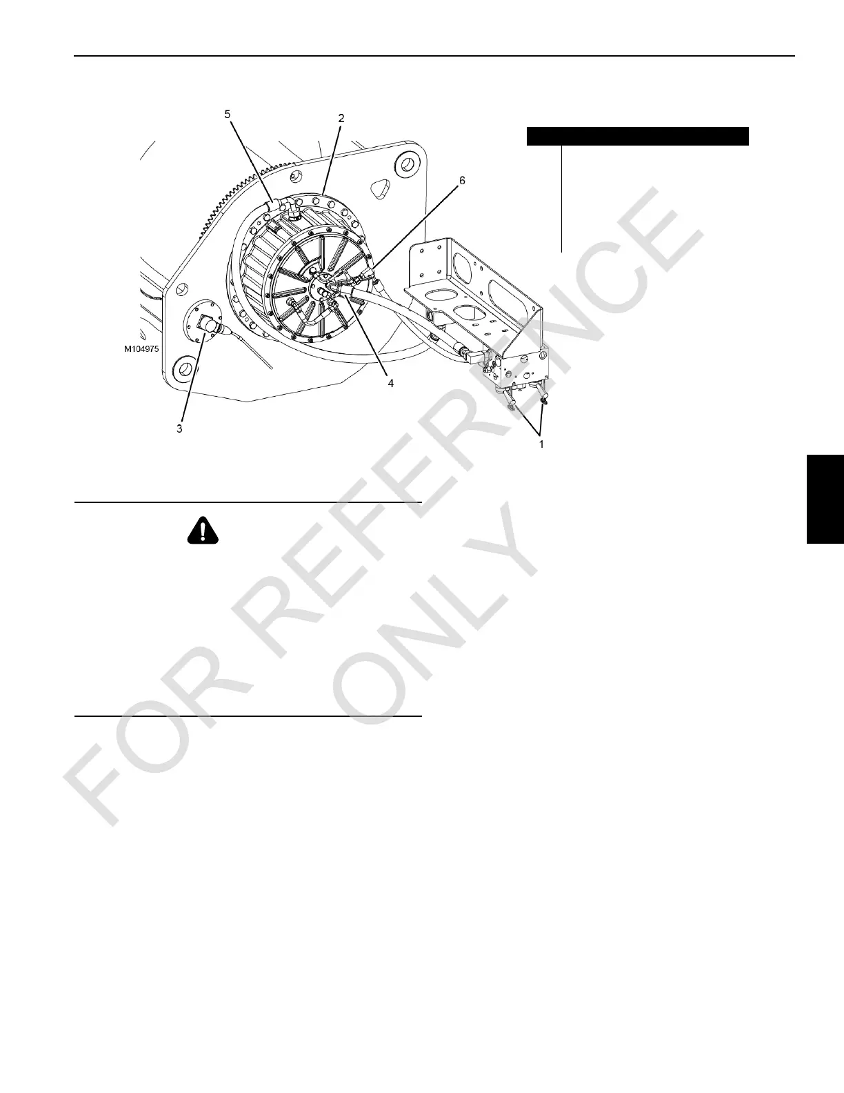
FIGURE 5-13
Item Description
1 Free Fall Selector Valves
2 Free Fall Brake (Drum 2 shown)
3 Free Fall Speed Senor
4 Cooling Flow In
5 Cooling Flow Out
6 Brake Release Pressure
WARNING
Falling Load Hazard
When the free fall mode is fully enabled, the load will fall
uncontrolled unless the brake pedal is applied.
Always be ready to apply the brake pedal so lowering
speed can be controlled.
If this is not done, the load can fall, possibly resulting in
injury or death.
To prevent the load from falling when free fall is selected
for a drum, latch down the free fall brake pedal.
 Loading...


