Manitowoc Published 12-10-19, Control # 258-05 4-31
MLC90A-1/MLC100-1 OPERATOR MANUAL SETUP AND INSTALLATION
Install Crane Counterweight (continued)
See Figure 4-17.
11. Disengage the counterweight pins (6, View D) using the
switch on the remote control.
12. Slowly raise the gantry (boom up using the Drum 4
thumbwheel on the remote control) to lift the crane
counterweight (1, View E) into position.
The boom butt will rise slightly and the boom stops will
fully compress during this step.
13. The pads (7, View E) on the front of the tray should
contact the rear of the crane first.
14. Use the arrow (8, View D) on the tray and the alignment
decal (9) to judge when the crane counterweight is high
enough to engage the counterweight pins.
15. Once the arrow (8, View D) points to the green area of
the alignment decal (9), release the counterweight pins
switch on the remote control to engage the
counterweight pins (6, View D).
NOTE If the crane counterweight is raised too high, the limit
switch (10, View D) will trip open to stop the gantry
and prevent the backhitch from fully extending. The
COUNTERWEIGHT TOO HIGH fault will come on in
the main display.
16. Verify that the counterweight pins are fully engaged.
17. Slowly lower the gantry (boom down using the Drum 4
thumbwheel on the remote control) to lower the crane
counterweight onto the pins.
18. Continue to lower the gantry until the handling pendants
(2, View F) can be unpinned from the handling links (3).
19. Unpin the pendants and store them on the
counterweight tray
See Figure 4-18
.
20. Fully raise the gantry (boom up using the Drum 4
thumbwheel on the remote control) until the cylinders
are fully extended and the backhitch links are tight.
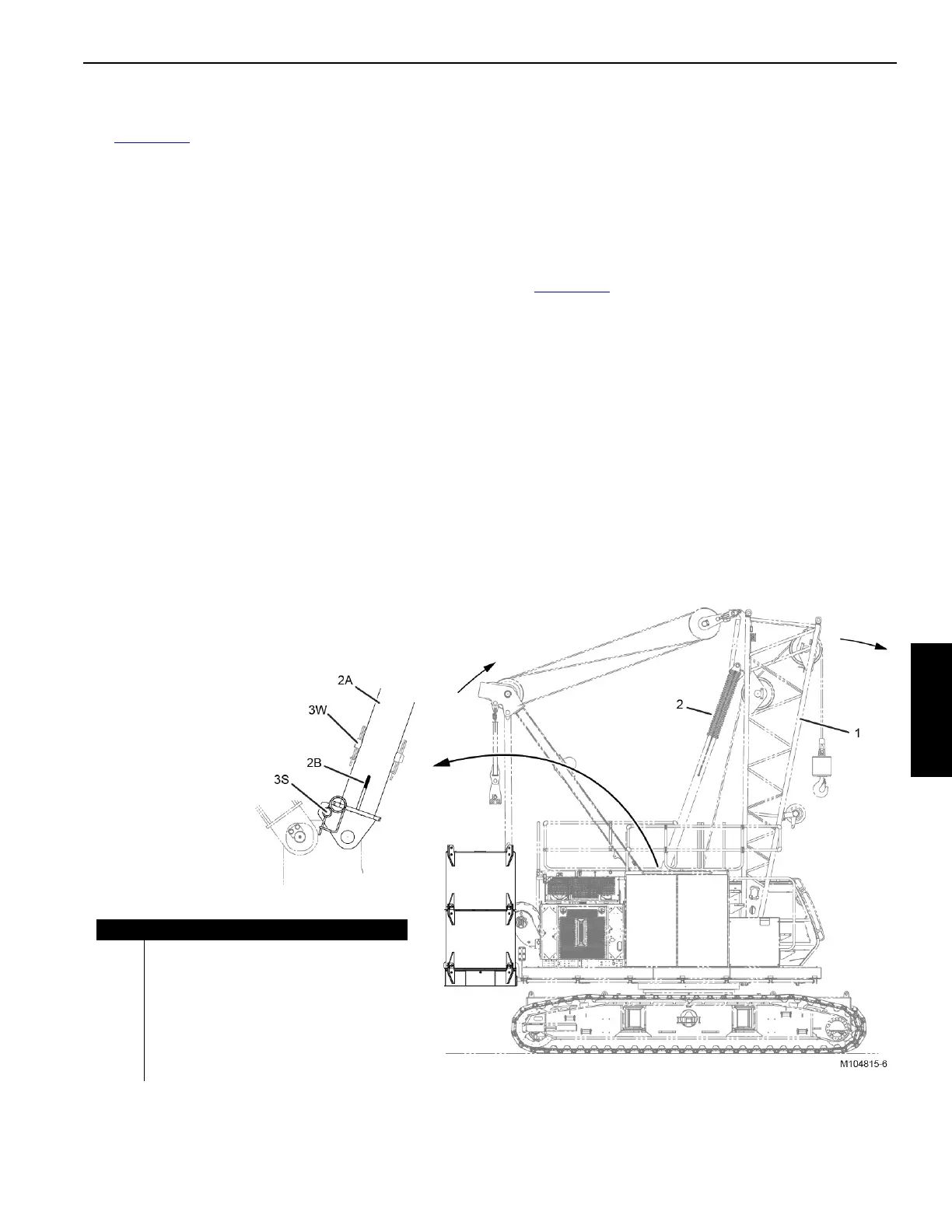
21. Boom up slightly using the Drum 4 thumbwheel on the
remote control so the hold-back pins (3) are loose.
22. Remove the hold-back pins (3) from the working holes
(W) in the boom stop tubes and install the pins in the
storage holes (S).
23. Turn OFF the SYNC switch on the remote control.
24. Lower the boom butt into the working range.
25. The remote control can now be disabled and stored.
Item Description
1 Boom Butt at 84°
2 Boom Stop Spring Compressed (qty 2)
2A Boom Stop Outer Tube (Qty 2)
2B Boom Stop Inner Tube (Qty 2)
3 Hold-Back Pin with Hair-Pin Cotter (Qty 2)
S Storage Holes
W Working Holes
Figure 4-18
 Loading...


